14
3. INPUT CONNECTOR SELECT BUTTON
3
3
USER CONTROLS
3.1 Control Names
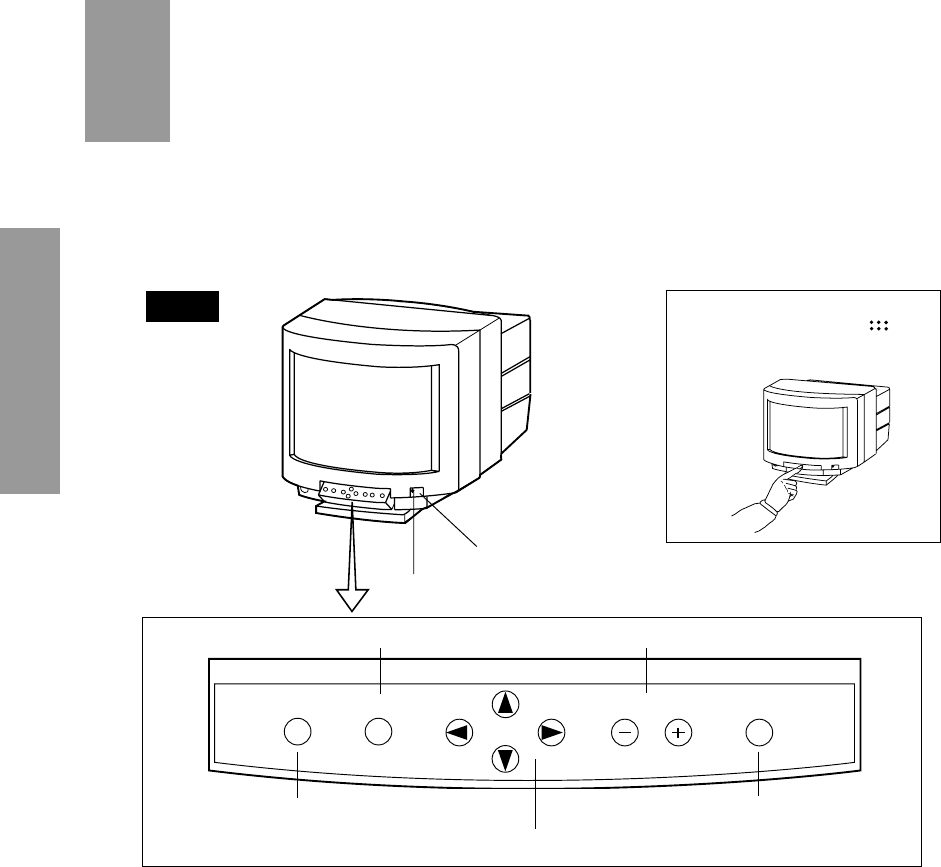
See Figure 6 and 7 for the location of the following user controls and indicators.
Each control is identified by number and is described individually on page 14.
1. POWER SWITCH
2. POWER-ON INDICATOR
[How to use the front control panel]
Press the button marked “
” on
the control panel to open.To close,
press it again.
5. FUNCTION SELECT BUTTONS
Figure 6
3.2 Function
1. POWER SWITCH: A push-on push-off switch for AC power.
2. POWER-ON INDICATOR: This indicator illuminates Green when AC power is on or Stand-
by mode, and illuminates Amber when suspend or power-off mode.
3. INPUT CONNECTOR SELECT BUTTON: Push the BNC/D-SUB button to select the input
signal BNC or D-SUB.
4. OSD OFF BUTTON: A push type button that is used to turn off the OSD.
5. FUNCTION SELECT BUTTONS: Push the select buttons to choose one of the functions that
is superimposed on the display screen.
6. FUNCTION ADJUST BUTTONS: Push the adjust buttons to adjust the image on the screen
that is selected via the function select buttons.
7. DEGAUSS BUTTON: A push type button that is used to eliminate possible color shading or
impurity.
7. DEGAUSS BUTTON
FRONT
6. FUNCTION ADJUST BUTTONS4. OSD OFF BUTTON
BNC/D-SUB OFF
BNC/D-SUB OFF
ADJUST DEGAUSS
ADJUST DEGAUSS
SELECT
SELECT


