


EN-37
ENGLISH
TV60, 480i(525i)
-
15.73 59.94 1024 x 576
-
TV50, 576i(625i)
-
15.63 50.00 1024 x 576
-
1080i 60 (1125i 60)
-
33.75 60.00 1024 x 576
-
*2
1080i 50 (1125i 50)
-
28.13 50.00 1024 x 576
-
480p (525p)
-
31.47 59.94 1024 x 576
-
*2
576p (625p)
-
31.25 50.00 1024 x 576
-
*2
720p 60 (750p 60)
-
45.00 60.00 1024 x 576
-
*2
720p 50 (750p 50)
-
37.50 50.00 1024 x 576
-
PC98 640 x 400 24.82 56.42 924 x 576 640 x 400
CGA70 640 x 400 31.47 70.09 924 x 576 640 x 400
CGA84 640 x 400 37.86 84.13 924 x 576 640 x 400
CGA85 640 x 400 37.86 85.08 924 x 576 640 x 400
VGA60 640 x 480 31.47 59.94 768 x 576 640 x 480
VGA72 640 x 480 37.86 72.81 768 x 576 640 x 480
VGA75 640 x 480 37.50 75.00 768 x 576 640 x 480
VGA85 640 x 480 43.27 85.01 768 x 576 640 x 480
SVGA56 800 x 600 35.16 56.25 768 x 576
-
SVGA60 800 x 600 37.88 60.32 768 x 576
-
*2
SVGA72 800 x 600 48.08 72.19 768 x 576
-
SVGA75 800 x 600 46.88 75.00 768 x 576
-
SVGA85 800 x 600 53.67 85.06 768 x 576
-
XGA43i 1024 x 768 35.52 86.96 768 x 576
-
XGA60 1024 x 768 48.36 60.00 768 x 576
-
*2
XGA70 1024 x 768 56.48 70.07 768 x 576
-
XGA75 1024 x 768 60.02 75.03 768 x 576
-
XGA85 1024 x 768 68.68 85.00 768 x 576
-
MAC13 640 x 480 35.00 66.67 768 x 576 640 x 480
MAC16 832 x 624 49.72 74.55 768 x 576
-
MAC19 1024 x 768 60.24 75.02 768 x 576
-
HP75 1024 x 768 62.94 74.92 768 x 576
-
SXGA60 1280 x 1024 60.02 63.98 720 x 576
-
*2
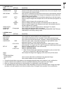
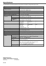
Specifi cation of RGB signals in each computer mode of the projector
Signal mode Resolution Horizontal Vertical Normal mode Real mode
(H x V) frequency (kHz) frequency (Hz) (H x V)*1 (H x V)
*1 : When ASPECT in the FEATURE menu is set to AUTO.
*2 : Available for the signal for DVI-D terminal.
Important:
• Some computers aren’t compatible with the projector.
• The projector's maximum resolution is 1024 x 576
pixels. It may not display images of higher resolutions
than 1024 x 576 correctly.
• If the resolution and frequency of your computer
aren't shown on the table, fi nd the compatible
resolution and frequency by changing the resolution
of your computer.
• Set COMPUTER INPUT in the SIGNAL menu to RGB
when inputting the HDTV signal as RGB signal.
• In the case of XGA, the right side of the image may
not appear. In this case, adjust TRACKING in the
SIGNAL menu.
• TV60 and TV50 are equivalent to 480i and 576i
respectively. When these signals are supplied to
the VIDEO or S-VIDEO signal, the signal mode is
indicated as TV60 or TV50. When they are supplied
to the COMPONENT terminal, the signal mode is
indicated as 480i or 576i.
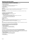
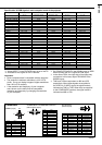
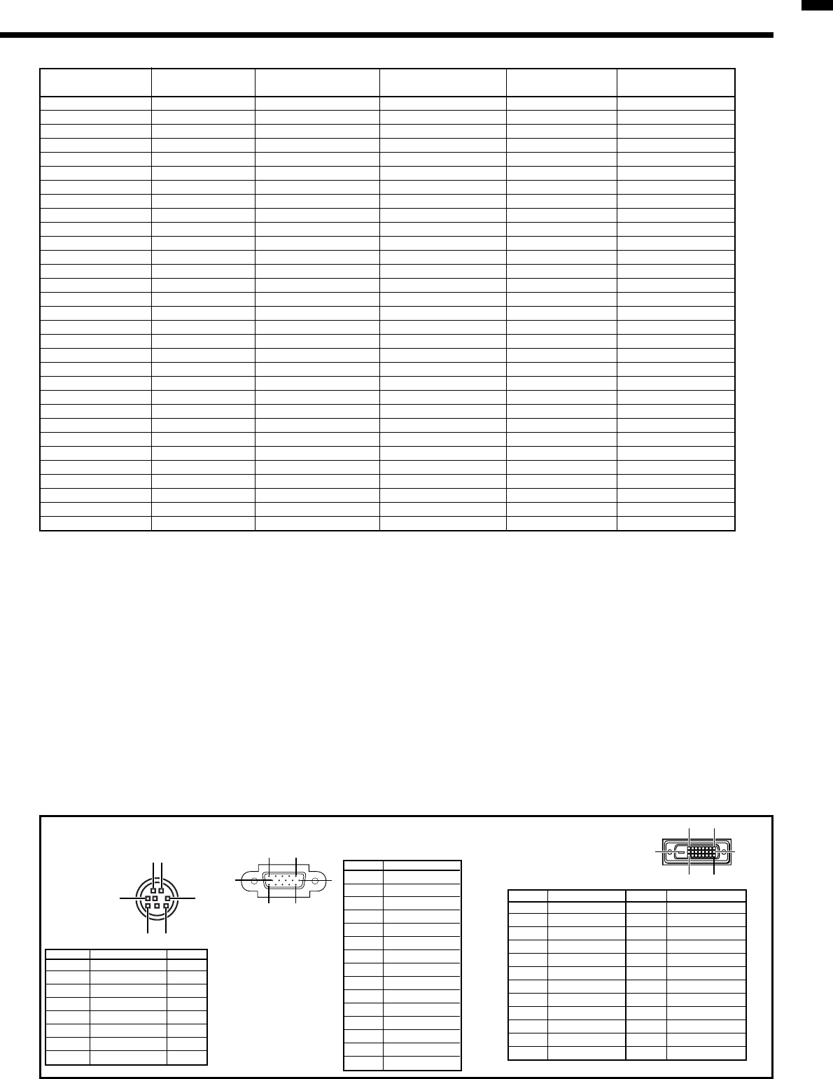
1 R(RED)/C
R
2
G(GREEN)/Y
3
B(BLUE)/C
B
4 GND
5 GND
6 GND
7 GND
8 GND
9 DDC 5V
10 GND
11 GND
12 DDC Data
13 HD/CS
14 VD
15 DDC Clock
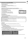
1 TXD IN
2
-
-
3
-
-
4 GND
-
5
-
-
6
-
-
7 RXD OUT
8
-
-
1
35
2
68
15
11
6
10
15
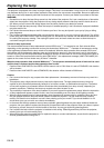
SERIAL (8-pin)
Pin No. Name I/O
COMPUTER IN / COMPONENT VIDEO IN
(Mini D-SUB 15-pin)
Pin No. Spec.
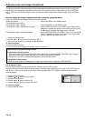
DVI-D (HDCP)
(DVI-D 24-pin)
PIN No.
SPEC
PIN No.
SPEC
1 DATA 2- 13
-
2 DATA 2+
14 +5V Power
3 DATA 2 Shield
15 Ground
4
-
16 Hot Plug Detect
5
-
17 DATA 0-
6 DDC Clock 18 DATA 0+
7 DDC Data 19 DATA 0 Shield
8
-
2
0
-
9 DATA 1- 21
-
10 DATA 1+ 22 Clock Shield
11 DATA 1 Shield 23 Clock+
12
-
24 Clock-
1724
16 9
8
1
Connectors