


PCL5100 features and upgrades
PCL5100 USER GUIDE 11
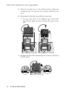
10. Separate the fan-sink from the processor by twisting the fan-
sink from side to side to loosen the grip of the thermal
bonding compound, then slide the fan-sink off to one side of
the processor.
WARNING
When you remove the fan-sink there will be a residual deposit of
thermal bonding compound on the bottom of the fan-sink and the top of
the processor. This compound can cause skin irritation and stain
clothing. Avoid prolonged or repeated contact with skin. Wash your
hands thoroughly with soap and water after handling. Avoid contact
with eyes and inhalation of fumes. Do not ingest.
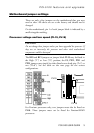
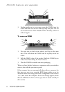
11. If you are replacing a Pentium processor with a
Pentium/MMX processor, you must remove the two jumpers
from jumper block PL18 (next to the socket). Use the
illustration at the start of this chapter to locate this jumper
block.
12. Ensure that the securing lever on the ZIF socket is still in the
upright position.
13. Take the upgrade processor out of its anti-static packaging.
Hold the processor by its edges and avoid touching the metal
pins.
◊ The processor and the ZIF socket are keyed to ensure that
the processor is installed in the correct orientation. (The
pin pattern is totally different at one corner.) It will only fit
into the socket one way.
14. Place the processor in the socket, making sure that it is
correctly aligned and that you do not bend or otherwise
damage the pins.
◊ If the processor is not big enough to occupy the entire
socket it should be positioned centrally.
CAUTION
If the processor is misaligned it will not go into the socket, and any
attempt to force it will damage the processor, the socket or both.