


PCL5100 features and upgrades
PCL5100 USER GUIDE 3
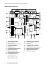
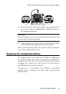
Motherboard jumper settings
There are only a few jumpers on the motherboard that you may
need to alter. All others are set at the factory and should not be
changed.
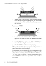
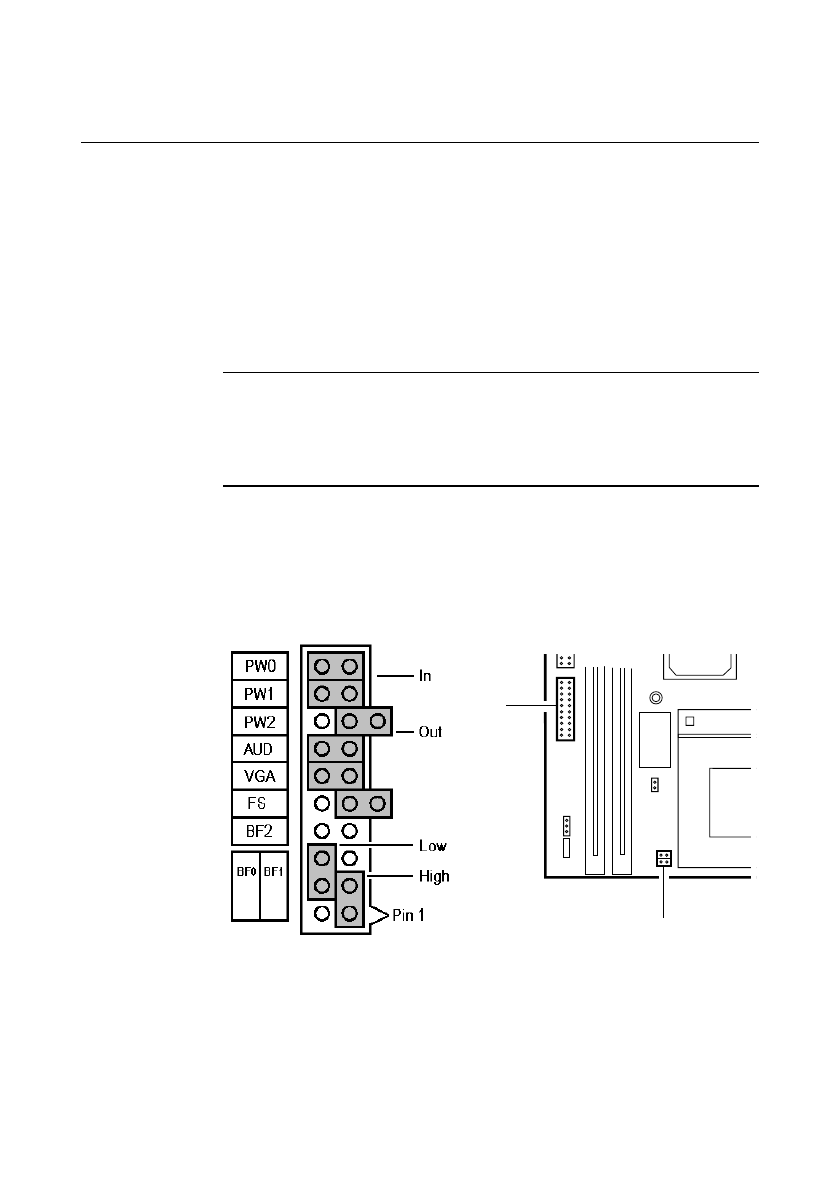
On the motherboard, pin 1 of each jumper block is indicated by a
small triangular marking.
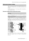
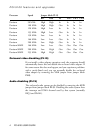
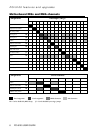
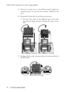
Processor voltage and bus speed (PL19, PL18)
CAUTION
Do not change these jumpers unless you have upgraded the processor. If
they are set incorrectly the processor and other vital motherboard
components could be destroyed.
The BF0 and BF1 jumpers on jumper block PL19 may be fitted in
the High (“1”) or Low (“0”) position; the FS, PW2, PW1 and
PW0 jumpers may simply be either fitted across both pins (“In”) or
not (“Out”). See the table on the next page for the correct
configurations.
PL19
PL 18
For Pentium processors only, two jumpers must also be fitted on
PL18. These jumpers must not be fitted for Pentium/MMX
processors.