9820/9830/9835 Service Manual Functional Description
12 TC9830SM Rev. B 7/98 Confidential July 1998
Printhead Locking
Printhead release knob is used to release the print
module from its open position.
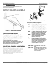
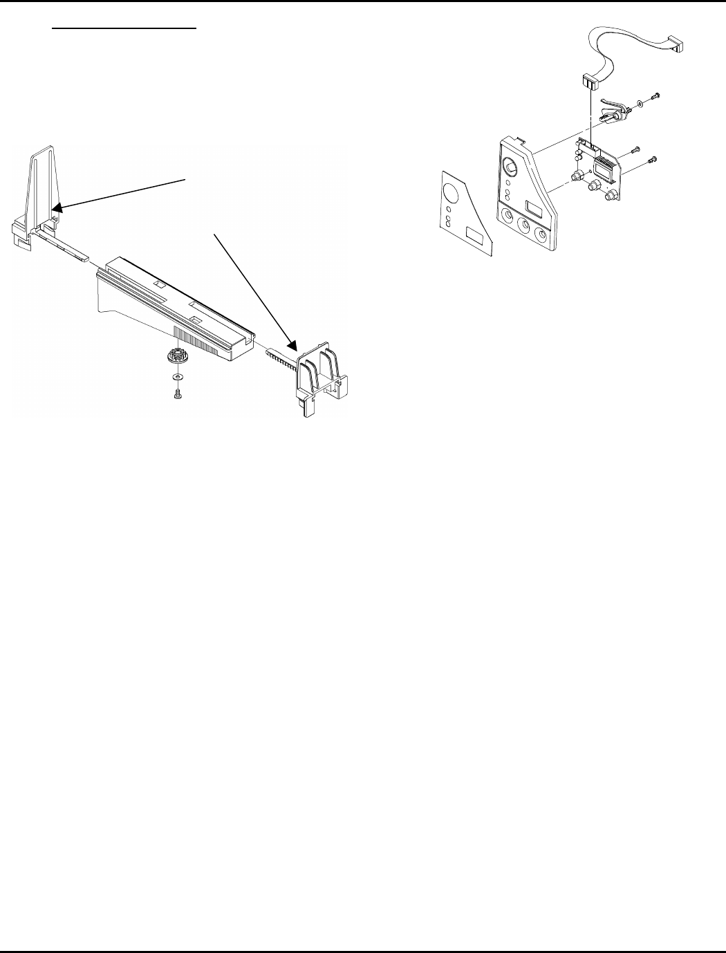
SUPPLY HOLDER ASSEMBLY
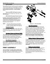
Figure 2- 3. Supply Holder Assembly
Functional Description
The supply holder module holds the supply roll in a
center-justified position to ensure optimum supply
tracking. The guides are gently pushed inward until
they center the roll and back off to the next detent
position when released.
The front guide pivots down for supply
loading/unloading. When loading fanfold supply, the
stack is placed behind the printer or under the table
and fed through the supply holder guides.
CONTROL PANEL ASSEMBLY
The Control Panel Assembly is mounted on the front
of the printer. The associated electronic components
are mounted on a circuit board behind the panel
fascia. A ground wire connects the board to the
chassis ground and a single wire harness connects it
to the Control Board Assy.
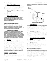
Figure 2- 4. Control Panel Assembly
Functional Description
LEDs
The three LEDs indicate general printer
status and activity.
LCD
The three-character LCD identifies
specific printer conditions through the
use of numeric codes. These codes are
listed and described in Appendix A.
Feed
In Normal mode, advances a label from
the printer. In Offline mode or Online
Diagnostic mode, prints a test label.
Pause
Stops the current batch from printing.
Printing resumes when Pause is
pressed a second time.
Clear
Cancels the current batch from being
printed if pressed for only a moment.
Cancels all batches associated with the
current format if pressed and held for
two seconds. Cancels some error
codes that appear on the LCD.
Feed + Pause
In Normal mode, prints a test
label.
Feed + Clear
In Diagnostics mode, places the
printer in data dump mode. See
Chapter 4, “Diagnostics” for
more information.
Inner Guide
Outer Guide


