Chapter 4 - V.22bis Commands
Multi-Tech Systems, Inc. MT2456SMI-22 SocketModem Developer’s Guide 39
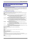
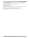
S16 - Test Mode Bit Mapped Options Status
S16 indicates the test in progress status.
Default: 0
Bit 0 Local analog loopback.
0 = Disabled. (Default)
1 = Enabled. (&T1)
Bit 1 Not used
Bit 2 Local digital loopback
0 = Disabled (default)
1 = Enabled (&T3)
Bit 3 Remote digital loopback (RDL) status
0 = Modem not in RDL
1 = RDL in progress
Bit 4 RDL requested (AT&T6)
0 = RDL not requested (default)
1 = RDL requested (&T6)
Bit 5 RDL with self test
0 = Disabled (default)
1 = Enabled (&T7)
Bit 6 Local analog loopback (LAL) with self test
0 = Disabled (default)
1 = Enable (&T8)
Bit 7 --- Not used
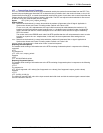
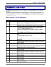
S19 - Reserved
S19 is supported for backwards compatibility only. No value can be written. Responds with default value.
Range: None
Default: 0
S20 - Reserved
S20 is supported for backwards compatibility only. No value can be written. Responds with default value.
Range: None
Default: 0
S21 - V.24/General Bit Mapped Options Status
S21 indicates the status of command options.
Default: 52 (34h) (00110100b)
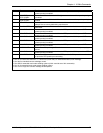
Bits 0 - 1 Telephone Jack Control (&Jn).
0 = &J0 selected. (Default)
1 = &J1 selected.
2 = &J2 selected.
3 = &J3 selected.
Bit 2 CTS behavior (&Rn).
0 = CTS tracks RTS (&R0).
1 = CTS always on (&R1). (Default)
Bits 3-4 DTR behavior (&Dn).
0 = &D0 selected.
1 = &D1 selected
2 = &D2 selected. (Default)
3 = &D3 selected.
Bit 5 RLSD behavior (&Cn).
0 = &C0 selected.
1 = &C1 selected. (Default)
Bit 6 DSR behavior (&Sn).
0 = &S0 selected. (Default)
1 = &S1 selected.
Bit 7 Long space disconnect (Yn).
0 = Y0. (Default)
1 = Y1.


