Chapter 4 - V.22bis Commands
Multi-Tech Systems, Inc. MT2456SMI-22 SocketModem Developer’s Guide 41
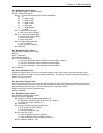
S27 - Bit Mapped Options Status
S27 indicates the status of command options.
Default: 73 (49h) (01001001b)
Bits 0,1,3 Synchronous/asynchronous selection (&Mn/&Qn).
31 0
0 0 0 = &M0 or &Q0.
0 0 1 = &M1 or &Q1.
0 1 0 = &M2 or &Q2.
0 1 1 = &M3 or &Q3.
10 0 = Reserved.
1 0 1 = &Q5. (Default)
11 0 = &Q6.
Bit 2 Leased line control (&Ln).
0 = Dial up line (&L0). (Default)
Bits 4 - 5 Internal clock select (&Xn).
0 = Internal clock (&X0). (Default)
1 = External clock (&X1).
2 = Slave clock (&X2).
Bit 6 ITU-T/Bell mode select (Bn).
0 = ITU-T mode (B0).
1 = Bell mode (B1). (Default)
Bit 7 Reserved.
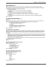
S28 - Bit Mapped Options Status
S28 indicates bit mapped options status.
Default: 0
Bits 0 - 1 Reserved.
Bit 2 Reserved (always 0).
Bits 3 - 4 Pulse dialing (&Pn)
0 = 39%-61% make/break ratio at 10 pulses per second (&P0). (Default)
1 = 33%-67% make/break ratio at 10 pulses per second (&P1).
2 = 39%-61% make/break ratio at 20 pulses per second (&P2).
3 = 33%-67% make/break ratio at 20 pulses per second (&P3).
Bit 5-7 Reserved
S29 - Flash Dial Modifier Time
S29 sets the length of time, in units of 10 ms, that the modem will go on-hook when it encounters the flash (!) dial
modifier in the dial string. S29 is a country dependent parameter. The S29 value cannot be changed using S29=XX.
Range: 0-255 10 ms intervals
Default: 70 (700 ms) for U.S.
S30 - Disconnect Inactivity Timer
S30 sets the length of time, in tens of seconds, that the modem will stay online before disconnecting when no data is
sent or received. In error-correction mode, any data transmitted or received will reset the timer. In other modes, any
data transmitted will reset the timer. The timer is inoperative in synchronous mode.
Range: 0-255 tens of seconds (0-2550 seconds)
Default: 0 (disabled)
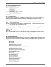
S31 - Bit Mapped Options Status
S31 indicates bit mapped options status.
Default: 192 (C0h) (11000000b)
Bit 0 Single line connect message enable/disable (\Vn).
0 = Messages controlled by S95, Wn and Vn (\V0). (Default)
1 = Single line connect message (\V1).
Bit 1 Reserved (0)
Bits 2-3 Error correction progress messages (Wn).
0 = DTE speed only (W0). (Default)
1 = Full reporting (W1).
2 = DCE (line) speed only (W2).
Bits 4-5 Caller ID (+VCID).
0 = Caller ID disabled (+VCID=0). (Default)
1 = Short (formatted) Caller ID enabled (+VCID=1).
2 = Long (unformatted) Caller ID enabled (+VCID=2).
Bits 6-7 Reserved (Default = 11b).


