


Appendix C: MVP428 Upgrade Card
Multi-Tech Systems, Inc. 138
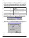
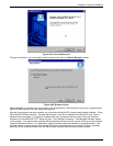
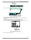
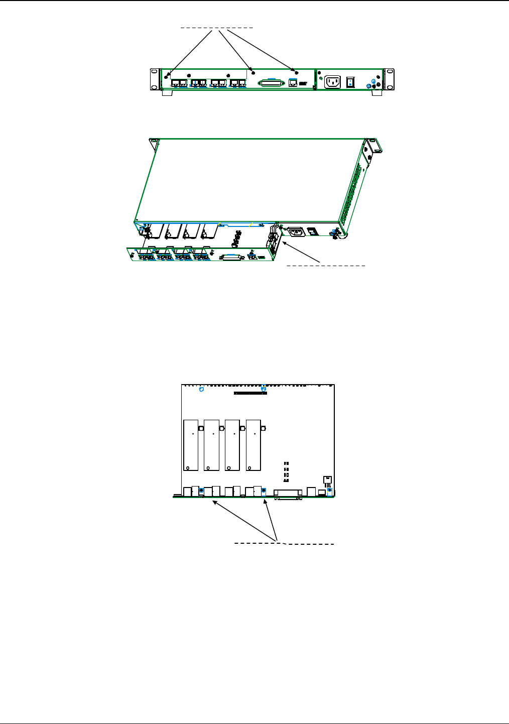
back panel screws (3)
Figure C-3: Remove screws from back panel
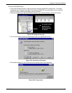
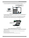
4. Slide the main circuit board out of the chassis far enough to unplug the power connector.
power connector
Figure C-4: Accessing the power connector
5. Unplug the power connector from the main circuit board.
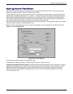
6. Slide the main circuit board completely out of the chassis and place on a non-conductive, static-safe
tabletop surface.
7. Remove mounting hardware (2 screws, 2 nuts, and 4 standoffs) from its package.
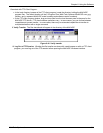
8. On the phone-jack side of the circuit card, three screws attach the circuit card to the back panel. Two of
these screws are adjacent to the four phone-jack pairs. Remove these two screws.
Screw locations (2)
at phone-jack edge
of board.
Figure C-5: Screws replaced with standoffs
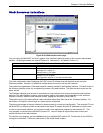
9. Replace these two screws with standoffs.