


Chapter 2: Installing and Cabling the MultiVOIP
Multi-Tech Systems, Inc. 14
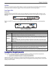
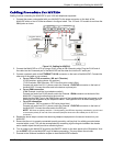
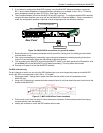
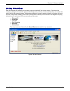
5. If you intend to configure the MultiVOIP remotely using the MultiVOIP Windows interface, connect an
RJ-11 phone cable between the Command Modem connector (not available on the –SS or –FX series)
and a receptacle served by a telco POTS line. See Figure 2-6 below.
6. The Command Modem is built into the MVP410 and 810 units only. To configure the MultiVOIP remotely
using its Windows interface, you must call into the MultiVOIP’s Command Modem. Once a connection is
made, the configuration process is identical to local configuration with the Windows interface.
COMMAND
10 BASET
E&M FXS/FXO
E&M FXS/FXO
E&M FXS/FXO E&M FXS/FXO
E&M FXS/FXO
E&M FXS/FXO
E&M FXS/FXO E&M FXS/FXO
COMMAND
MODEM
Telco POTS Line
Grounding Screw
ETHERNET
Command Modem connector
for remote configuration
MVP-410/810
Rear Panel
Figure 2-6: MVP410/810 connections for ground & modem
7. Ensure that the unit is properly connected to earth ground by verifying that it is reliably grounded when
mounted within a rack.
8. This can be accomplished by connecting a grounding wire between the chassis grounding screw (see
Figure 2-6) and a metallic object that will provide an electrical ground.
9. Turn on power to the MultiVOIP by placing the ON/OFF switch on the back panel to the ON position. Wait
for the Boot LED on the MultiVOIP to go off before proceeding. This may take a few minutes.
10. Proceed to Chapter 3 to load the MultiVOIP software.
For DID channels only
For any channel on which you are using the DID interface type, you must change the jumper on the MultiVOIP
circuit card. DID is not supported on the –SS or –FX models.
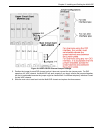
1. Disconnect power. Unplug the AC power cord from the wall outlet or from the receptacle on the
MultiVOIP unit.
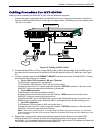
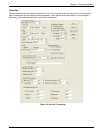
2. Using a #1 Phillips driver, remove the three screws (at back of unit) that attach the main circuit card to the
chassis of the MultiVOIP.
Figure 2-7: MVP-410/810 Rear Screw Locations
3. Pull the main circuit card out about 5 inches (the power connection to the board prevents it from being
removed entirely from the chassis).
4. Identify the channels on which the DID interface will be used.