Chapter 1 Installing and Configuring the SCXI-1127/1128
© National Instruments Corporation 1-9 SCXI-1127/1128 User Manual
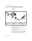
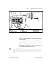
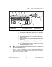
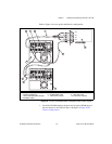
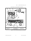
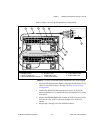
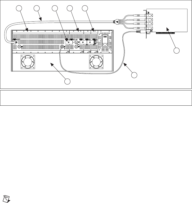
Figure 1-5.
12-Slot Configuration Parts Locator Diagram
1. Install the 8-slot HVAB-backplane adapter behind slots 5 through 12.
2. Install additional 2-slot and 1-slot HVAB-backplane adapters behind
slots 1 through 4 if needed.
3. Install the 8-position HVAB plugs to connect the HVAB-backplane
adapters as needed.
4. Connect the HV8-BAN4 cable from the DMM to the HVAB connector
behind slot 12.
5. Connect the SH9MD-9MD cable from the DMM to the AUX IN
connector behind slot 5.
6. You can install any additional SCXI-1127 modules in any slot that has
an HVAB-backplane adapter behind it.
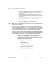
Notes
Do not connect the SH9MD-9MD cable to the AUX IN connector behind slot 4 on
the 2-slot HVAB-backplane adapter.
An SCXI-1127/1128 is required in slot 12 to establish communications with the chassis.
If slot 12 is empty, the system will not operate. It is this module that you must specify in
MAX as the module cabled to the DMM.
1 8-Slot HVAB-Backplane Adapter
2 HV8-BAN4 Cable
3 8-Position HVAB Plug
4 2-Slot HVAB-Backplane Adapter
5 1-Slot HVAB-Backplane Adapter
6 NI 4060 for PCI
7 SH9MD-9MD Cable
8 12-Slot SCXI Chassis
AB0+
AB0–
AB2+
AB2–
6
8
7
1 32 4 5


