Appendix D SCXI-1127/1128 Front Connector
© National Instruments Corporation D-5 SCXI-1127/1128 User Manual
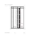
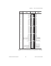
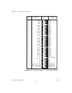
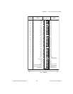
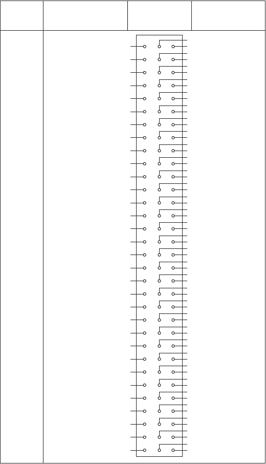
Figure D-4.
SCXI-1127/1128 Front Connector Pin Assignments to Create
an 4
×
8Matrix
32
31
30
29
28
27
26
25
24
23
22
21
20
19
18
17
16
15
14
13
12
11
10
9
8
7
6
5
4
3
2
1
C2+
C2–
C5+
C5–
C0+
C0–
C3+
C3–
C6+
C6–
C1+
C1–
C4+
C4–
C7+
C7–
C2+
C2–
C5+
C5–
R0+
R0–
R3+
R3–
CJS–
+5 V (ISO)
NC
NC
NC
+5 V (Non-Isolated)
GND (Non-Isolated)
SCANADVD
C0+
C1+
C3+
C4+
C6+
C7+
C1+
C2+
C4+
C5+
C7+
C0+
C2+
C3+
C5+
C6+
C0+
C1+
C3+
C4+
C6+
C7–
R1+
R2+
CJS+
+5 V (ISO)_HVAB_EN
NC
NC
NC
NC
GND (Non-Isolated)
GND (Non-Isolated)
C0–
C1–
C3–
C4–
C6–
C7–
C1–
C2–
C4–
C5–
C7–
C0–
C2–
C3–
C5–
C6–
C0–
C1–
C3–
C4–
C6–
C7+
R1–
R2–
CJS–
1_WIRE_LO_REF
NC
NC
NC
GND (Non-Isolated)
GND (Non-Isolated)
EXT_TRIG_IN
Pin
Number
Signal
Name
Column
A B C
Signal
Name


