© National Instruments Corporation D-1 SCXI-1127/1128 User Manual
D
SCXI-1127/1128
Front Connector
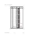
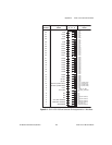
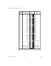
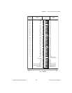
This appendix contains connector diagrams for the SCXI-1127/1128
switch cards. The diagrams also show the signal names that are used
when the modules are in 2-wire mode, 1-wire mode, 4-wire mode, and
4 × 8 matrix configuration.
When you connect a custom terminal block or cable it is important that you
incorporate the safety interlock scheme into the terminal block/cable. You
do this by connecting the +5 V (ISO)_HVAB_EN signal to the +5 V (ISO)
signal. These signals are shown in the following figures. Refer to Table D-1
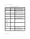
for descriptions of signal names.


