


Chapter 2 Installation and Verification
© National Instruments Corporation 2-7 PCI Serial for Windows Me/9x
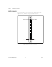
serial hardware, PORT1 refers to the top port, PORT2 refers to the
next port down, and so on.
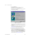
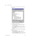
7. Run the diagnostic utility, as follows: select
Start»Programs»National Instruments Serial»diagnostics.
The diagnostic utility verifies that your serial driver is installed
properly, that the configuration of your hardware does not conflict
with anything else in your system, and that the serial driver can
communicate with your hardware correctly.
If the test is successful, your serial hardware and software are installed
properly. If the test fails, refer to Appendix C, Troubleshooting and
Common Questions, to troubleshoot the problem.
After you verify the hardware and software installation, continue to the next
section, Connect the Cables.
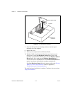
Connect the Cables
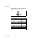
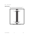
For the two-port PCI serial boards, you can use the standard
DB-9 connector found on most serial cables. To use the DB-9 connector
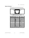
with the four-port PCI serial boards, you need the 10-position modular jack
to DB-9 cable, which is available from National Instruments. You can also
use a DB-25 connector with the four-port PCI serial boards by ordering the
10-position modular jack to DB-25 converter cable from National
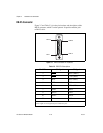
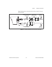
Instruments. The eight-port PCI serial boards include a pig tail cable
adapter, providing eight standard DB-9 connectors. The 16-port board
includes a break out box, providing 16 standard DB-9 connectors.
Note
To achieve the specified isolation voltage for four-port isolated PCI serial boards,
use only the 10-position modular jack to DB-9 cable that is included in your four-port
isolated PCI serial board kit.