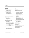
Index
© National Instruments Corporation I-3 PCI Serial for Windows Me/9x
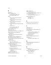
I
installation
getting started, 1-2
PCI serial board installation (figure), 2-4
serial hardware, 2-3
serial software, 2-1
verification, 2-1
verifying hardware installation, 2-5
interrupt request level, C-1
freeing, C-1
introduction, 1-1
isolated four-port boards, D-2
isolated two-port boards, D-1
L
LabVIEW, 1-4
using with serial hardware, 1-5
LabWindows/CVI, 1-4
using with serial hardware, 1-5
legacy boards, C-4
resolving resource conflicts with, C-4
M
maximum supported baud rate, C-7
modular jack connector, 2-9
pin descriptions (table), 2-9
pin locations (figure), 2-9
multidrop network using terminating resistors
(figure), A-5
N
naming National Instruments serial ports, C-6
standard DOS-based addresses
(table), C-7
National Instruments Web support, E-1
NI Developer Zone, E-1
NI-Serial setup screen (figure), 2-2
null-modem cabling in a DTE-to-DTE
interface (figure), A-7
O
optional equipment, 1-2
overview of serial hardware, 1-2
overview of serial software, 1-4
P
parity, 3-3
PCI serial board installation (figure), 2-4
PCI-232, 1-2
PCI-485, 1-2, 2-15
advanced transceiver control for, 4-1
setting transceiver control mode, 4-3
transceiver mode control bytes
(table), 4-4
transceiver mode control modes
(table), 4-2
two-wire mode: DTR
controlled, 4-2
two-wire mode: DTR
with Echo, 4-2
two-wire mode: TXRDY
auto
control, 4-3
pin descriptions
100-pin connector pin descriptions
(figure), 2-14
100-pin connector pin descriptions
(table), 2-15
68-pin connector pin descriptions
(figure), 2-12
68-pin connector pin descriptions
(table), 2-13
DB-25
connector, 2-10
connector pin descriptions
(table), 2-10
connector pin locations (figure), 2-10
DB-9
100-pin description (table), 2-15


