


Appendix B Cabling Requirements
Getting Started with CAN for Windows NT B-4
©
National Instruments Corporation
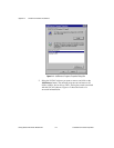
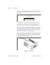
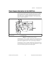
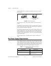
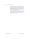
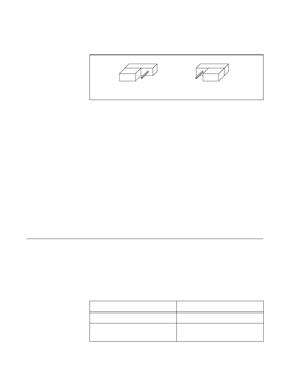
Figure B-5 shows how to configure your jumpers for internal or external
power supplies.
Figure B-5.
Power Source Jumpers
The CAN physical layer is still isolated regardless of the power source
chosen.
The PCMCIA-CAN and PCMCIA-CAN/2 are available with two types of
cable. The DeviceNet (bus powered) cable requires that the CAN physical
layer be powered from the bus cable power.
The internal-powered cable supplies power to the CAN physical layer from
the host computer. The V+ pin is not connected to any internal signals, but
the corresponding pins on the 9-pin D-Sub and the 5 pin Combicon-style
connectors are still connected. The V– pins serves as the reference ground
for the isolated signals.
The CAN physical layer is isolated from the computer in both types of
cable.
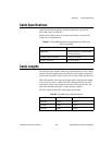
Bus Power Supply Requirements
If the CAN physical layer is powered from a bus power supply, the power
supply should be a DC power supply with an output of 10 V to 30 V. The
power requirements for the CAN ports for Bus-Powered configurations are
shown in Table B-1. You should take these requirements into account when
determining requirements of the bus power supply for the system.
Table B-1.
Power Requirements for the CAN Physical Layer for
Bus-Powered Versions
Characteristic Specification
Voltage Requirement V+ 10-30 VDC
Current Requirement 40 mA typical
100 mA maximum
INT EXT
a. Internal Power Mode
INT EXT
b. External Power Mode
(Device Net)
123123