


Chapter 2 Installation and Configuration
©
National Instruments Corporation 2-7 FieldPoint FP-1000/FP-1001 User Manual
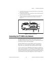
The FP-1000 does not use RS-232 hardware handshaking, but it still
asserts the RTS and DSR signals for host computers or software that
may require these signals. A host computer that does not use these
signals does not need to connect to them.
RS-485 Interface Specifications
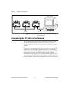
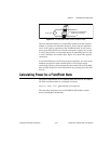
RS-485 specifies a maximum cabling distance of 4000 ft, but
improvements in line drivers and cabling technology often allow you to
design your network beyond the recommendations of the specification.
If even longer distances are desirable, you can use RS-485 repeaters.
An RS-485 stub is created when you tap the RS-485 backbone to form
a T-junction. RS-485 stubs must be less than 3 in. long. However, you
can create longer stubs by using an RS-485 repeater to start the stub,
ensuring that the repeater is close to the junction.
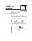
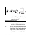
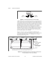
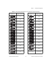
The RS-485 connector is a 5-pin Combicon connector whose pinout is
shown in Figure 2-8.
Figure 2-8.
RS-485 Connector Pinout for the FP-1000 and FP-1001
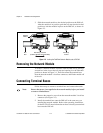
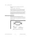
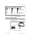
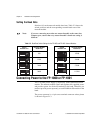
RS-485 Network Termination and Biasing
An RS-485 network must be terminated at each end of the network, but
not anywhere else. At each end bank, termination resistors should be
installed between the RX pair and between the TX pair. These network
terminating resistors are nominally 120 Ω and are provided in your kit.
To install them, twist the resistor leads with the RS-485 signal wires and
then insert them into the RS-485 Combicon adapter as shown in
Figure 2-9. The 120 Ω resistor in the figure is a terminating resistor.
RX–
RX+
TX–
TX+
GND
12345