


Chapter 2 Installation and Configuration
FieldPoint FP-1000/FP-1001 User Manual 2-8
©
National Instruments Corporation
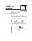
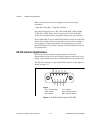
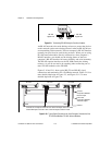
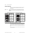
Figure 2-9. Terminating RS-485 Using the Combicon Adapter
An RS-485 network also needs biasing resistors to protect the devices
on the network against noise during intervals when no RS-485 drivers
are transmitting on the network. The host computer’s RS-485 interface
normally has provision for such biasing resistors. When you are using
FP-1001 network modules directly connected to a host computer’s
RS-485 interface, you should use the biasing feature of the host
computer’s RS-485 interface for better reliability and noise immunity.
The RS-485 repeater interface on the FP-1000 already has biasing
resistors, so you do not need to do anything when connecting one or
more FP-1001 modules to the FP-1000.
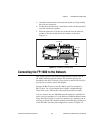
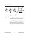
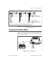
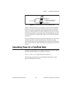
Figures 2-10 and 2-11 show typical RS-232 and RS-485 signal
connections and termination for a FieldPoint network. Figure 2-10 is a
more detailed depiction of Figure 2-5, and Figure 2-11 is a more
detailed depiction of Figure 2-6.
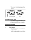
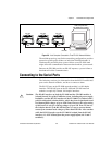
Figure 2-10. Typical Signal Connections for Host Computer Connected to One
FP-1000 and Multiple FP-1001 Network Modules
120 Ω 120 Ω
+
–
+
–
RS-485
Signal Pair
RS-485
Signal Pair
RX+
RX-
GND
TX-
TX+
To Host
Computer's RS-232
Receive Input
From Host
Computer's RS-232
Transmit Output
Ground
FP-1001 FP-1001 FP-1000
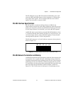
120Ω
TX
RX
TX RX
RX TX
120Ω
120Ω
120Ω
Connect the TX outputs of the FP-1001 to the RX inputs of the FP-1000,
and the RX inputs of the FP-1001 to the TX outputs of the FP-1000.