


Table of Contents
©
National Instruments Corporation vii FieldPoint FP-1000/FP-1001 User Manual
Figure 2-8. RS-485 Connector Pinout for the FP-1000 and FP-1001......................2-7
Figure 2-9. Terminating RS-485 Using the Combicon Adapter ..............................2-8
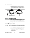
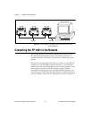
Figure 2-10. Typical Signal Connections for Host Computer Connected to
One FP-1000 and Multiple FP-1001 Network Modules........................2-8
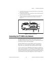
Figure 2-11. Typical Signal Connections for Host Computer Connected to
Multiple FP-1001 Network Modules.....................................................2-9
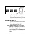
Figure 2-12. Address and Baud Rate Switch..............................................................2-9
Figure 2-13. FP-1000 and FP-1001 Power Connector Pinout....................................2-13
Figure 3-1. LEDs on the FP-1000 and FP-1001.......................................................3-7
Tables
Table 2-1. Network Address Switch Settings for the FP-1000 and FP-1001
Network Modules ..................................................................................2-11
Table 2-2. Baud Rate Switch Settings for the FP-1000 and FP-1001
Network Modules ..................................................................................2-12
Table 3-1. Module Configuration Results After HotPnP Replacement..................3-6
Table 3-2. STATUS LED Flashes and Corresponding Error Conditions...............3-8