


Chapter 2 Installation and Configuration
FieldPoint FP-1000/FP-1001 User Manual 2-12
©
National Instruments Corporation
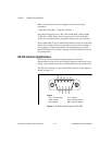
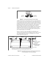
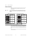
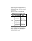
Setting the Baud Rate
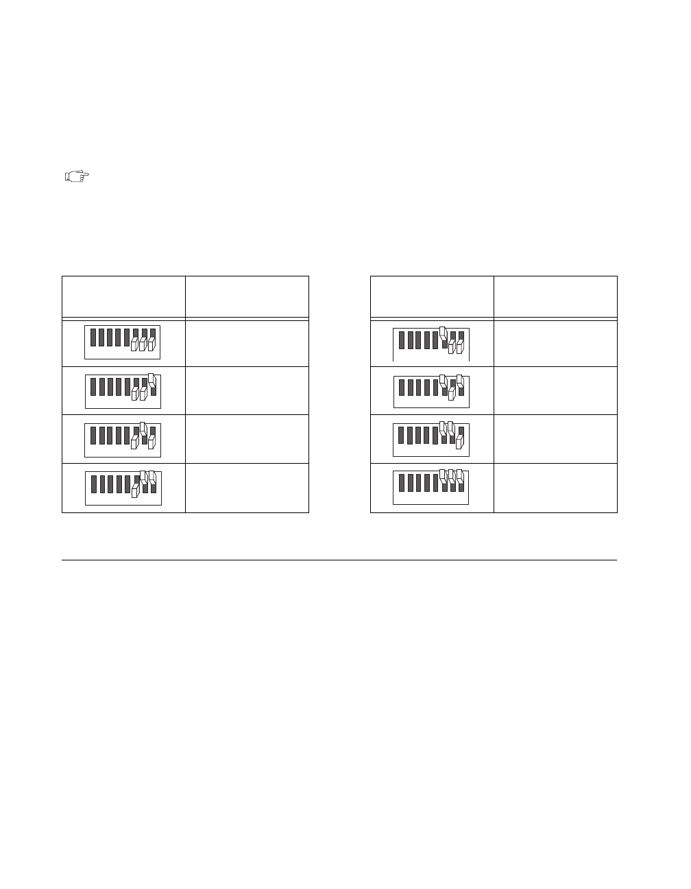
Switches 6-8 set the network module baud rate. Table 2-2 shows the
switch positions and the corresponding network baud rates of the
network module.
Note: If you are connecting more than one network module to the same host
computer port, ensure that every network module’s baud rate setting is
identical.
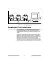
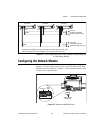
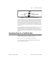
Connecting Power to the FP-1000 or FP-1001
An 11-30 VDC power supply is required by each FieldPoint network
module. The network module filters and regulates this supplied power
and provides power for all the I/O modules in the bank. Therefore you
need not provide power separately to each FieldPoint I/O module in the
bank.
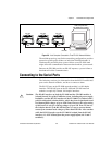
The power connector is a 4-pin screw terminal connector whose pinout
is shown in Figure 2-13.
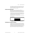
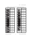
Table 2-2.
Baud Rate Switch Settings for the FP-1000 and FP-1001 Network Modules
Switch
Positions 6-8
Network Module
Baud Rate
Switch
Positions 6-8
Network Module
Baud Rate
300 19200
1200 38400
2400 57600
9600 115200
12345678
12345678
12345678
12345678
12345678
12345678
12345678
12345678