


Chapter 2 Installation and Configuration
©
National Instruments Corporation 2-9 FieldPoint FP-1000/FP-1001 User Manual
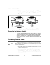
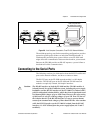
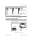
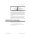
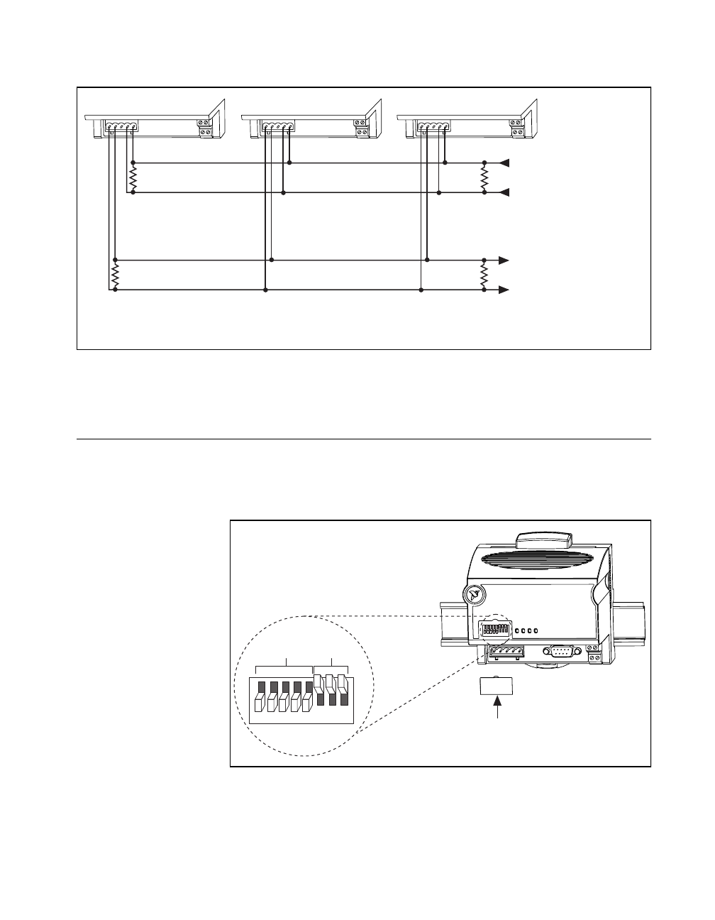
Figure 2-11. Typical Signal Connections for Host Computer Connected to Multiple
FP-1001 Network Modules
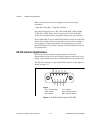
Configuring the Network Module
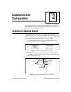
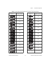
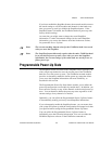
Figure 2-12 shows the 8-position switch on the FP-1000 and FP-1001
FieldPoint network modules. Switches 1-5 set the network address, and
switches 6-8 set the baud rate.
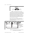
Figure 2-12. Address and Baud Rate Switch
120Ω
120Ω
120Ω
120Ω
From Host
Computer's RS-485
Transmit Output Pair (TX)
To Host
Computer's RS-485
Receive Input Pair (RX)
FP-1001 FP-1001
FP-1001
+
+
–
–
RX TX RX TX RX TX
Connect the TX outputs of the host computer to the RX inputs of the FP-1001,
and the RX inputs of the host computer to the TX outputs of the FP-1001.
12345678
12345678
Address
Baud
Rate
Switch Cover
(Removed)