


Chapter 4 Arb Operation
DAQArb 5411 User Manual 4-18
©
National Instruments Corporation
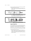
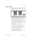
Note: Marker output signals are an important feature to trigger other
instruments or devices at a specified time while a waveform generation is
in progress.
Analog Output
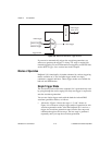
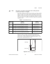
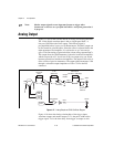
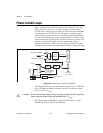
Figure 4-17 shows the essential blocks of analog waveform generation.
The 12-bit digital waveform data is fed to a high-speed DAC. A
low-pass filter filters the DAC output. This filtered signal is
pre-amplified before it goes to a 10 dB attenuator. The DAC output can
be fine-tuned for gain and offset. Since the offset is adjusted before the
main attenuators and amplifier, it is referred to as pre-attenuation
offset. This fine-tuning of gain and offset is done using separate DACs.
The output from the 10 dB attenuator is then fed to the main amplifier,
which can provide ±5 V levels into 50 Ω. An output relay can switch
between ground level and the main amplifier. The output of this relay is
fed to a series of passive attenuators. The output of the attenuators is fed
through a selectable output impedance of 50 or 75 Ω to the I/O
connector.
Figure 4-17.
Analog Output and SYNC Out Block Diagram
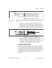
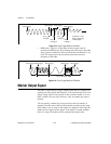
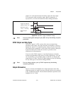
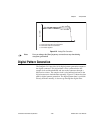
Figure 4-18 shows the timing relationships of the trigger input,
waveform output, and marker output. T
d1
is the pulse width on the
trigger signal. T
d2
is the time delay from trigger to output on Arb
DAC
Gain
DAC
Pre Amp
Main Amp
Filter
Low-Pass
10 db
Attenuator
Attenuators
Output
Enable
25 Ω
ARB
Selector
50 Ω/75 Ω
Offset
DAC
12
Clock
Level
DAC
+
-
SYNC
Comparator
50 Ω
50 Ω
(63 dB in 1 dB steps)