


Chapter 4 Arb Operation
DAQArb 5411 User Manual 4-26
©
National Instruments Corporation
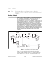
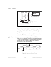
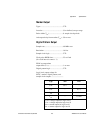
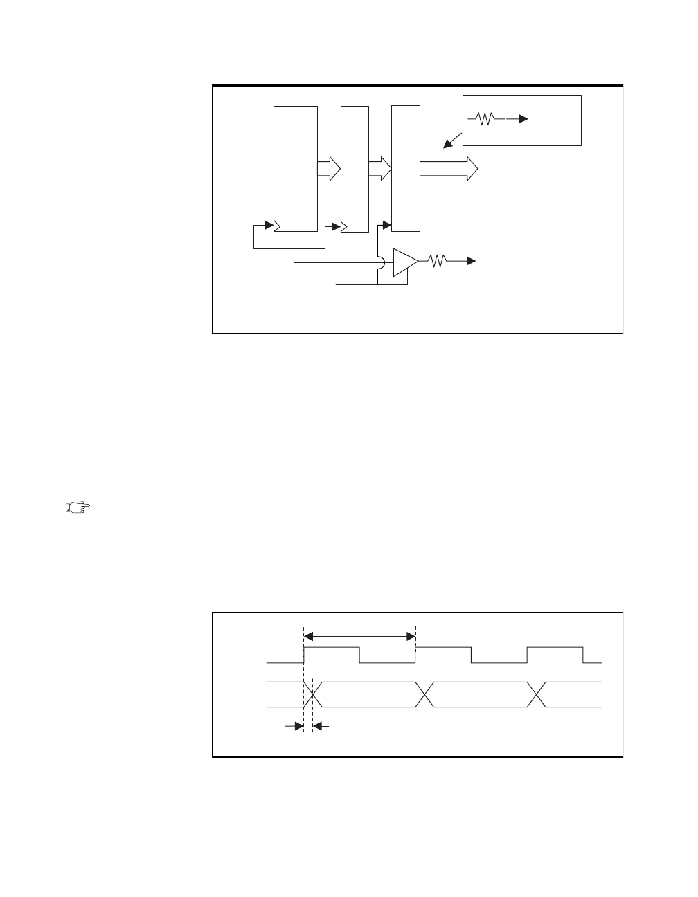
Figure 4-23. Digital Pattern Generator Data Path
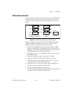
You can enable or disable digital pattern generation through software.
All linking and looping capabilities are available for digital pattern
generation, as well. If you select DDS mode, the DDS data appears at
the digital I/O connector.
You can use digital pattern generation to test digital devices such as
serial and parallel DACs and to emulate protocols.
Note: At computer power-up and reset, pattern generation is disabled.
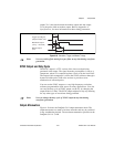
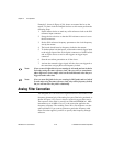
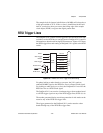
Figure 4-24 shows the timing waveforms for digital pattern generation;
t
clk
is the clock time period and t
co
is time delay from clock to output
on pattern lines, such as PA <0..15>. Refer to the Appendix A,
Specifications, for these timing parameters.
Figure 4-24. Digital Pattern Generation Timing
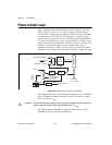
Waveform Memory
16
(16-Bit) Register
Output Buffer
16
Digital Pattern Out
OE*
Clock
Pattern Enable
Clock Out
Line Out
80 Ω
50 Ω
*Output Enable
Clock
t
co
t
clk
D
n
D
n+1
D
n+2
Data