Index
©
National Instruments Corporation I-5 DAQArb 5411 User Manual
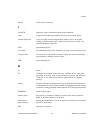
mechanical, A-6
operational modes, A-4
sine spectral purity, A-2
SYNC out, A-4
timing I/O, A-3
triggers
digital trigger, A-4
RTSI, A-4
voltage output, A-1 to A-2
stages
instructions, 4-6
maximum number (note), 4-6
waveform linking and looping, 4-5
waveform staging block diagram, 4-6
staging list, 4-3, 4-5
stepped trigger mode
Arb mode, 4-14 to 4-15
DDS mode, 4-15
SYNC connector, 3-3
SYNC output
analog output and SYNC out block
diagram, 4-18
duty cycle, 4-19
changing, 4-19
example (figure), 3-3
software control of, 3-3
purpose and use, 4-19
routing to RTSI lines, 3-3
specifications, A-4
system requirements, 1-2
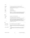
T
technical support, C-1 to C-2
telephone and fax support, C-2
timing I/O specifications, A-3
transistor-transistor-logic (TTL), SYNC
connector, 3-3
trigger specifications
digital trigger, A-4
RTSI, A-4
triggering, 4-11 to 4-16
burst trigger mode, 4-15 to 4-16
continuous trigger mode, 4-13 to 4-14
modes of operation, 4-12 to 4-16
single trigger mode, 4-12 to 4-13
stepped trigger mode, 4-14 to 4-15
trigger sources, 4-11 to 4-12
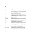
U
update rate, 4-3
V
VirtualBench software
overview, 1-3 to 1-4
VirtualBench-Arb (note), 4-2
VirtualBench-Function Generator
(note), 4-2
voltage output specifications, A-1 to A-2
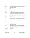
W
waveform generation, 4-2 to 4-3. See also Arb
mode; direct digital synthesis (DDS) mode.
data path block diagram, 4-3
overview, 4-2 to 4-3
process of waveform generation
(figure), 4-8
specifications, A-3
VirtualBench-Arb (note), 4-2
VirtualBench-Function Generator
(note), 4-2
waveform linking and looping, 4-5 to 4-8
block diagram for waveform staging, 4-7
concept of linking and looping
(figure), 4-6


