


HPC167064 Operating Modes
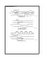
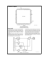
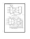
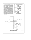
SINGLE CHIP NORMAL MODE
In this mode the HPC167064 functions as a self-contained
microcomputer (see
Figure 15
) with all memory (RAM and
EPROM) on-chip It can address internal memory only con-
sisting of 16 kbytes of EPROM (C000 to FFFF) and
512 bytes of on-chip RAM and Registers (0000 to 02FF)
The ‘‘illegal address detection’’ feature of the WATCHDOG
is enabled in the Single-Chip Normal mode and a WATCH-
DOG Output (WO
) will occur if an attempt is made to access
addresses that are outside of the on-chip EPROM and RAM
range of the device Ports A and B are used for IO func-
tions and not for addressing external memory The EXM pin
and the EA bit of the PSW register must both be logic ‘‘0’’ to
enter the Single-Chip Normal mode
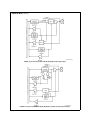
EXPANDED NORMAL MODE
The Expanded Normal mode of operation enables the
HPC167064 to address external memory in addition to the
on-chip ROM and RAM (see Table I) WATCHDOG illegal
address detection is disabled and memory accesses may
be made anywhere in the 64 kbyte address range without
triggering an illegal address condition The Expanded Nor-
mal mode is entered with the EXM pin pulled low (logic ‘‘0’’)
and setting the EA bit in the PSW register to ‘‘1’’
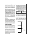
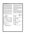
TABLE I HPC167064 Operating Modes
Operating Mode
EXM EA Memory
Pin Bit Configuration
Single-Chip Normal 0 0 C000–FFFF On-Chip
Expanded Normal
01
C000–FFFF On-Chip
0300–BFFF Off-Chip
Single-Chip ROMless 1 0 C000–FFFF Off-Chip
Expanded ROMless 1 1 0300–FFFF Off-Chip
SINGLE-CHIP ROMless MODE
In this mode the on-chip EPROM of the HPC167064 is not
used The address space corresponding to the on-chip
EPROM is mapped into external memory so 16k of external
memory may be used with the HPC167064 (see Table I)
The WATCHDOG circuitry detects illegal addresses (ad-
dresses not within the on-chip EPROM and RAM range)
The Single-Chip ROMless mode is entered when the EXM
pin is pulled high (logic ‘‘1’’) and the EA bit is logic ‘‘0’’
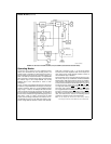
EXPANDED ROM MODE
This mode of operation is similar to Single-Chip ROMless
mode in that no on-chip ROM is used however a full
64 kbytes of external memory may be used The ‘‘illegal
address detection’’ feature of WATCHDOG is disabled The
EXM pin must be pulled high (logic ‘‘1’’) and the EA bit in the
PSW register set to ‘‘1’’ to enter this mode
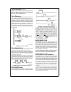
Wait States
The internal EPROM can be accessed at the maximum op-
erating frequency with one wait state With 0 wait states
internal ROM accesses are limited to f
C
max The
HPC167064 provides four software selectable Wait States
that allow access to slower memories The Wait States are
selected by the state of two bits in the PSW register Addi-
tionally the RDY input may be used to extend the instruc-
tion cycle allowing the user to interface with slow memories
and peripherals
TLDD11046–23
FIGURE 15 Single-Chip Mode
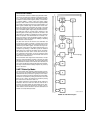
Power Save Modes
Two power saving modes are available on the HPC167064
HALT and IDLE In the HALT mode all processor activities
are stopped In the IDLE mode the on-board oscillator and
timer T0 are active but all other processor activities are
stopped In either mode all on-board RAM registers and
IO are unaffected
HALT MODE
The HPC167064 is placed in the HALT mode under soft-
ware control by setting bits in the PSW All processor activi-
ties including the clock and timers are stopped In the
HALT mode power requirements for the HPC167064 are
minimal and the applied voltage (V
CC
) may be decreased
without altering the state of the machine There are two
ways of exiting the HALT mode via the RESET
or the NMI
The RESET
input reinitializes the processor Use of the NMI
input will generate a vectored interrupt and resume opera-
tion from that point with no initialization The HALT mode
can be enabled or disabled by means of a control register
HALT enable To prevent accidental use of the HALT mode
the HALT enable register can be modified only once
IDLE MODE
The HPC167064 is placed in the IDLE mode through the
PSW In this mode all processor activity except the on-
board oscillator and Timer T0 is stopped As with the HALT
mode the processor is returned to full operation by the
RESET
or NMI inputs but without waiting for oscillator stabi-
lization A timer T0 overflow will also cause the HPC167064
to resume normal operation
Note If an NMI interrupt is received during the instruction which puts the
device in Halt or Idle Mode the device will enter that power saving
mode The interrupt will be held pending until the device exits that
power saving mode When exiting Idle mode via the T0 overflow the
NMI interrupt will be serviced when the device exits Idle If another
NMI interrupt is received during either Halt of Idle the processor will
exit the power saving mode and vector to the interrupt address
HPC167064 Interrupts
Complex interrupt handling is easily accomplished by the
HPC167064’s vectored interrupt scheme There are eight
possible interrupt sources as shown in Table II
16