Timer Overview (Continued)
(Clock Input16) rate It is used for WATCHDOG logic high
speed event capture and to exit from the IDLE mode Con-
sequently it cannot be stopped or written to under software
control Timer T0 permits precise measurements by means
of the capture registers I2CR I3CR and I4CR A control bit
in the register TMMODE configures timer T1 and its associ-
ated register R1 as capture registers I3CR and I2CR The
capture registers I2CR I3CR and I4CR respectively record
the value of timer T0 when specific events occur on the
interrupt pins I2 I3 and I4 The control register IRCD pro-
grams the capture registers to trigger on either a rising edge
or a falling edge of its respective input The specified edge
can also be programmed to generate an interrupt (see
Fig-
ure 19
)
The HPC167064 provides an additional 16-bit free running
timer T8 with associated input capture register EICR (Ex-
ternal Interrupt Capture Register) and Configuration Regis-
ter EICON EICON is used to select the mode and edge of
the EI pin EICR is a 16-bit capture register which records
the value of T8 (which is identical to T0) when a specific
event occurs on the EI pin
The timers T2 and T3 have selectable clock rates The
clock input to these two timers may be selected from the
following twosources anexternal pinorderived internallyby
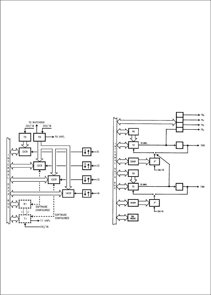
TLDD11046–27
FIGURE 19 Timers T0 T1 and T8
with Four Input Capture Registers
dividing the clock input Timer T2 has additional capability of
being clocked by the timer T3 underflow This allows the
user to cascade timers T3 and T2 into a 32-bit timercoun-
ter The control register DIVBY programs the clock input to
timers T2 and T3 (see
Figure 20
)
The timers T1 through T7 in conjunction with their registers
form Timer-Register pairs The registers hold the pulse du-
ration values All the Timer-Register pairs can be read from
or written to Each timer can be started or stopped under
software control Once enabled the timers count down and
upon underflow the contents of its associated register are
automatically loaded into the timer
SYNCHRONOUS OUTPUTS
The flexible timer structure of the HPC167064 simplifies
pulse generation and measurement There are four syn-
chronous timer outputs (TS0 through TS3) that work in con-
junction with the timer T2 The synchronous timer outputs
can be used either as regular outputs or individually pro-
grammed to toggle on timer T2 underflows (see
Figure 20
)
Timerregister pairs 4–7 form four identical units which can
generate synchronous outputs on Port P (see
Figure 21
)
TLDD11046–28
FIGURE 20 Timers T2–T3 Block
20


