


HPC167064 Interrupts (Continued)
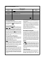
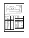
TABLE II Interrupts
Vector
Interrupt Source
Arbitration
Address Ranking
FFFFFFFE RESET 0
FFFDFFFC Nonmaskable external on rising edge of I1 pin 1
FFFBFFFA External interrupt on I2 pin 2
FFF9FFF8 External interrupt on I3 pin 3
FFF7FFF6 External interrupt on I4 pin 4
FFF5FFF4 Overflow on internal timers 5
FFF3FFF2 Internal on the UART transmitreceive complete or external on EXUI 6
FFF1FFF0 External interrupt on EI pin 7
Interrupt Arbitration
The HPC167064 contains arbitration logic to determine
which interrupt will be serviced first if two or more interrupts
occur simultaneously The arbitration ranking is given in Ta-
ble II The interrupt on RESET
has the highest rank and is
serviced first
Interrupt Processing
Interrupts are serviced after the current instruction is com-
pleted except for the RESET
which is serviced immediately
RESET
and EXUI are level-LOW-sensitive interrupts and EI
is programmable for edge-(RISING or FALLING) or level-
(HIGH or LOW) sensitivity All other interrupts are edge-sen-
sitive NMI is positive-edge sensitive The external interrupts
on I2 I3 and I4 can be software selected to be rising or
falling edge External interrupt (EXUI
) is shared with UART
interrupt This interrupt is level-low sensitive To select this
interrupt disable the ERI and ETI UART interrupt bits in the
ENUI register To select the UART interrupt leave this pin
floating or tie it high
Interrupt Control Registers
The HPC167064 allows the various interrupt sources and
conditions to be programmed This is done through the vari-
ous control registers A brief description of the different con-
trol registers is given below
INTERRUPT ENABLE REGISTER (ENIR)
RESET
and the External Interrupt on I1 are non-maskable
interrupts The other interrupts can be individually enabled
or disabled Additionally a Global Interrupt Enable Bit in the
ENIR Register allows the Maskable interrupts to be collec-
tively enabled or disabled Thus in order for a particular
interrupt to request service both the individual enable bit
and the Global Interrupt bit (GIE) have to be set
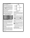
INTERRUPT PENDING REGISTER (IRPD)
The IRPD register contains a bit allocated for each interrupt
vector The occurrence of specified interrupt trigger condi-
tions causes the appropriate bit to be set There is no indi-
cation of the order in which the interrupts have been re-
ceived The bits are set independently of the fact that the
interrupts may be disabled IRPD is a ReadWrite register
The bits corresponding to the maskable external interrupts
are normally cleared by the HPC167064 after servicing the
interrupts
For the interrupts from the on-board peripherals the user
has the responsibility of resetting the interrupt pending flags
through software
The NMI bit is read only and I2 I3 and I4 are designed as to
only allow a zero to be written to the pending bit (writing a
one has no affect) A LOAD IMMEDIATE instruction is to be
the only instruction used to clear a bit or bits in the IRPD
register This allows a mask to be used thus ensuring that
the other pending bits are not affected
INTERRUPT CONDITION REGISTER (IRCD)
Three bits of the register select the input polarity of the
external interrupt on I2 I3 and I4
Servicing the Interrupts
The Interrupt once acknowledged pushes the program
counter (PC) onto the stack thus incrementing the stack
pointer (SP) twice The Global Interrupt Enable bit (GIE) is
copied into the CGIE bit of the PSW register it is then reset
thus disabling further interrupts The program counter is
loaded with the contents of the memory at the vector ad-
dress and the processor resumes operation at this point At
the end of the interrupt service routine the user does a
RETI instruction to pop the stack and re-enable interrupts if
the CGIE bit is set or RET to just pop the stack if the CGIE
bit is clear and then returns to the main program The GIE
bit can be set in the interrupt service routine to nest inter-
rupts if desired
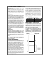
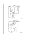
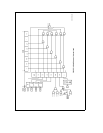
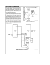
Figure 18
shows the Interrupt Enable Logic
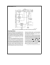
RESET
The RESET input initializes the processor and sets Ports A
and B in the TRI-STATE condition and Port P in the LOW
state RESET
is an active-low Schmitt trigger input The
processor vectors to FFFFFFFE and resumes operation at
the address contained at that memory location (which must
correspond to an on board location) The Reset vector ad-
dress must be between C000 and FFFF when emulating the
HPC16064 and between E000 and FFFF when emulating
the HPC16003
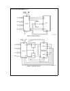
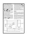
Timer Overview
The HPC167064 contains a powerful set of flexible timers
enabling the HPC167064 to perform extensive timer func-
tions not usually associated with microcontrollers The
HPC167064 contains nine 16-bit timers Timer T0 is a
free-running timer counting up at a fixed CKI16
18