


Chapter 2 Hardware Overview
© National Instruments Corporation 2-3 NI PCI-1410 User Manual
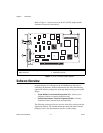
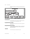
Digital Filter and LUT
The digital filter removes chrominance from a composite color video signal
that conforms to either PAL or NTSC. The output of the digital filter passes
through the 1,024 × 10-bit lookup table (LUT). You can configure the LUT
to implement simple imaging operations such as contrast enhancement,
data inversion, gamma correction, or other user-defined transfer functions.
Onboard Memory
The NI 1410 has 16 MB of SDRAM for temporarily storing image data
being transferred to the system memory through the PCI bus. The memory
can store multiple image buffers.
Scatter-Gather DMA Controllers
The NI 1410 uses three independent onboard direct memory access (DMA)
controllers. The DMA controllers transfer data between the onboard
SDRAM memory buffer and the PCI bus. Each of these controllers
supports scatter-gather DMA, which allows the controllers to reconfigure
on-the-fly. This functionality enables the NI 1410 to perform continuous
image transfers directly to either contiguous or fragmented memory
buffers.
PCI Interface
The NI 1410 implements the PCI interface with a National Instruments
custom application-specific integrated circuit (ASIC), the PCI MITE. The
PCI interface can transfer data at a maximum rate of 132 MB/s in bus
master mode.
Genlock Circuit and SYNC Mux
The genlock circuit receives the incoming video signal and generates
PCLK, HSYNC, and VSYNC signals for use by the acquisition and control
circuitry. The NI 1410 can lock to the standard RS-170/NTSC and
CCIR/PAL video signals as well as progressive scan and VGA
(640 × 480 resolution) signals. The genlock circuit on the NI 1410 also can
lock to external HSYNC and VSYNC or CSYNC signals, as well as
additional nonstandard formats.