


Chapter 2 Hardware Overview
© National Instruments Corporation 2-5 NI PCI-1410 User Manual
• External HSYNC/VSYNC (HLOCK only) Mode—In external
HSYNC/VSYNC (HLOCK only) mode, the NI 1410 receives the
external HSYNC and VSYNC signals and internally generates the
PCLK signal. In this mode, the NI 1410 genlock circuitry uses only the
HSYNC signal for locking. You can use this mode to acquire from
asynchronously reset cameras that output a continuous HSYNC.
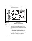
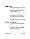
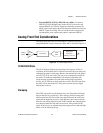
Analog Front End Considerations
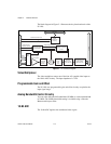
The analog front end of the NI 1410 features a calibrated gain circuit,
programmable DC-restore circuit, and 10-bit ADC as shown in Figure 2-2.
Figure 2-2. NI 1410 Analog Front End
10-Bit/8-Bit Mode
The NI 1410 always digitizes the incoming video signal to 10 bits of
resolution. In 10-bit mode, the NI 1410 has four fixed, full-scale ranges for
calibrating the gain for each range. Because the nominal full-scale ranges
are 0.20, 0.35, 0.70, and 1.40 V, the gain is not continuously variable in
this mode. To maintain compatibility with existing acquisition code
and processing algorithms used with other analog image acquisition
devices, the NI 1410 has an 8-bit mode that converts the 10-bit data from
the ADC to 8-bit data in the LUT after gain correction and any digital
filtering has occurred.
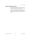
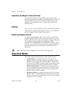
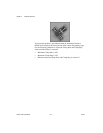
Clamping
The NTSC camera file sets the default values of Clamp Start and Clamp
Stop to 106 and 116, respectively. These settings place the clamp pulse,
which restores the DC level of the video signal, between the color burst
signal and the beginning of active video. Because some cameras deviate
from the exact timing required by the NTSC standard, the clamping pulse
may intersect either the color burst or the active video portions of the
signal. If this occurs, an acquired image may appear to have dark and light
bands, as in the following image.
DC-restore
1 of 4
Gain
Analog
Video
10-bit
ADC
Digital Gain
Correction,
Filtering, and LUT
10- or 8-bit