


Chapter 3 Signal Connections
NI PCI-1410 User Manual 3-2 ni.com
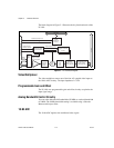
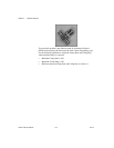
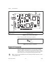
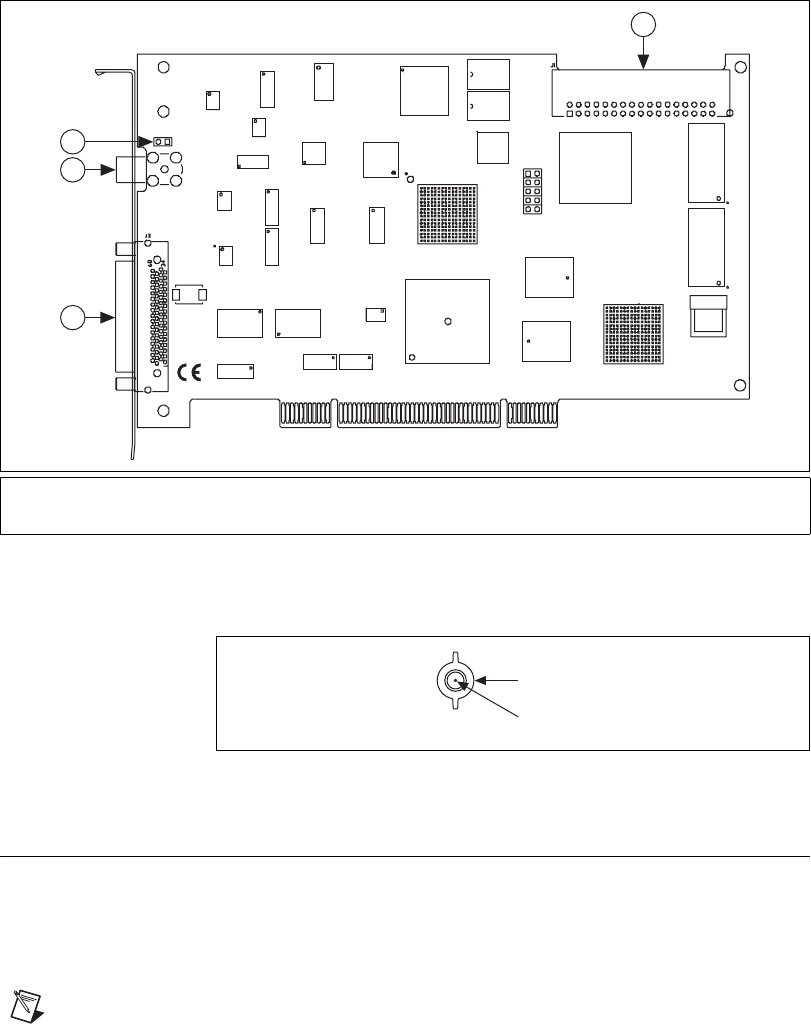
Figure 3-1. NI PCI-1410 Parts Locator Diagram
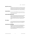
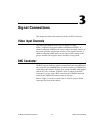
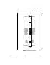
Figure 3-2 shows the BNC connector pin assignments.
Figure 3-2. BNC Connector Pin Assignment
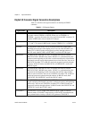
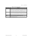
Digital I/O Connector
The 68-pin VHDCI connector connects to all video signals (VIDEO0,
VIDEO1, VIDEO2, and VIDEO3), the external digital I/O lines, triggers,
and external signals. To access these connections, you can build your own
custom cable or use one of the optional National Instruments cables.
Note If you are using the VIDEO0 connection on the 68-pin VHDCI connector, you must
unplug the BNC cable.
1 68-Pin VHDCI Connector 3 W1 Jumper
2 BNC Connector 4 RTSI Bus Connector
4
3
1
2
NI PCI-1410
COPYRIGHT 2004
NATIONAL INSTRUMENTS
©
GND
VIDEO0+