


Chapter 3 I/O Information
© National Instruments Corporation 3-7 NI PXI-8183 User Manual
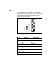
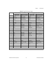
Table 3-5. Parallel Port Connector Signals
Pin
Default Configuration (LPT) Floppy Configuration
1
Signal Name Signal Description Signal Name Signal Description
1 BUSY* Device Busy MTR1* Motor on Disk 1
2 SLCTIN* Select Input Step* Step Pulse
3 ACK* Acknowledge DS1* Drive Select 1
4 FAULT* Fault WDATA* Write Disk Data
5 ERROR Error HDSEL* Head Select
6 PD0 Data Bit 0 Index* Index Pulse Input
7 PD1 Data Bit 1 TRK0* Track 0
8 PD 2 Data Bit 2 WRTPRT* Write Protected
9 PD3 Data Bit 3 RDATA* Read Disk Data
10 PD4 Data Bit 4 DSKCHG* Disk Change
11 PD5 Data Bit 5 Not Used —
12 PD6 Data Bit 6 MTR0* Motor on Disk 0
13 PD7 Data Bit 7 Not Used —
14 INIT* Initialize Printer DIR* Step Direction
15 STROBE* Strobe DS0* Drive Select 0
16 SLCT Select WGATE* Write Gate
17 AUTOFD Auto Line Feed DRVDEN0* Density Select
18 +5V +5 V +5V +5 V
19–35 GND Ground GND Ground
36 NC Not Connected NC Not Connected
1
Refer to the BIOS Setup section of Chapter 2, Installation and Configuration.