


— 2 —
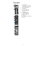
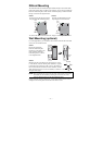
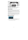
Panel Layout
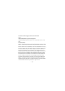
V1 V2 INPUTS: 24 VDC
PWR2
V2+
V2-
V1-
V1+
FAULT
PWR1
12345678
ON DIP
PORT ALARM
Top Panel View
1
2
3
4
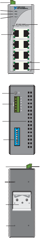
Rear Panel View
1
2
13
12
12
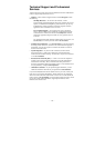
Front Panel View
8
9
10
2
5
6
7
11
1. Grounding screw
2. Terminal block for power inputs
PWR1/PWR2 and relay output
3. Heat dissipation orifices
4. DIP switches
5. Power input PWR1 LED
6. Power input PWR2 LED
7. Fault LED
8. 10/100BaseT(X) Port
9. TP port’s 100 Mbps LED
10. TP port’s 10 Mbps LED
11. Model Name
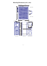
12. Screw holes for wall mounting kit
13. DIN-rail Kit