


— 8 —
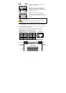
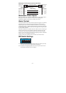
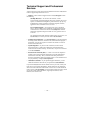
RJ45 (8-pin) to RJ45 (8-pin) Cross-Over Cable Wiring
Cross-Over Cable
RJ45 Plug Pin 1
Switch Port
(NIC Port)
RJ45
Connector
RJ45
Connector
Tx+
Tx-
Rx+
Rx-
(Rx+)
(Rx-)
(Tx+)
(Tx-)
(Tx+)
(Tx-)
(Rx+)
(Rx-)
Switch Port
(NIC Port)
Cable Wiring
3 1
6 2
1 3
2 6
Rx+
Rx-
Tx+
Tx-
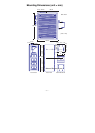
Redundant Power Inputs
Both power inputs can be connected simultaneously to live DC power sources.
If one power source fails, the other live source acts as a backup, and
automatically supplies all of the NI UES-3880’s power needs.
Alarm Contact
The NI UES-3880 has one Alarm Contact located on the top panel. For detailed
instructions on how to connect the Alarm Contact power wires to the two
middle contacts of the 6-contact terminal block connector, see the Wiring the
Alarm Contact section. A typical scenario would be to connect the Fault circuit
to a warning light located in the control room. The light can be set up to switch
on when a fault is detected.
The Alarm Contact has two terminals that form a Fault circuit for connecting to
an alarm system. The two wires attached to the Fault contacts form an open
circuit when (1) the NI UES-3880 has lost power from one of the DC power
inputs, or (2) one of the ports for which the corresponding PORT ALARM DIP
Switch is set to ON is not properly connected.
If neither of these two conditions occurs, the Fault circuit will be closed.
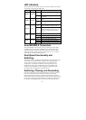
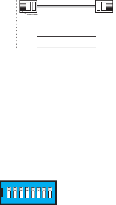
DIP Switch Settings
12345678
ON DIP
ON: Enables the corresponding PORT Alarm. If the port’s link fails, the relay
will form an open circuit and the fault LED will light up.
Off: Disables the corresponding PORT Alarm. The relay will form a closed
circuit and the Fault LED will never light up.