


— 5 —
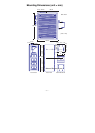
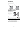
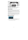
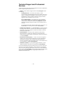
STEP 3:
Once the screws are fixed in the
wall, insert the four screw heads
through the large parts of the
keyhole-shaped apertures, and then
slide the NI UES-3880
downwards, as indicated. Tighten
the four screws for added stability.
⇒
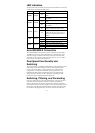
Wiring Requirements
WARNING
Do not disconnect modules or wires unless the power supply has
been switched off or the area is known to be non-hazardous. The
devices may only be connected to the supply voltage shown on
the type plate.
The devices are designed for operation with a Safety Extra-Low
Voltage. Thus, they may only be connected to the supply voltage
connections and to the signal contact with the Safety Extra-Low
Voltages (SELV) in compliance with IEC950/ EN60950/
VDE0805.
WARNING
Substitution of components may impair suitability for Class I,
Division 2, and Zone 2. These devices must be supplied by an
SELV source as defined in Low Voltage Directive 73/23/EEC
and 93/68/EEC.
WARNING
This unit is a built-in type. When the unit is installed in another
piece of equipment, the equipment enclosing the unit must
comply with fire enclosure regulation IEC 60950/EN60950 (or
similar regulation).
WARNING
Safety First!
Be sure to disconnect the power cord before installing and/or
wiring your Switch.
Calculate the maximum possible current in each power wire and
common wire. Observe all electrical codes dictating the
maximum current allowable for each wire size.
If the current goes above the maximum ratings, the wiring could
overheat, causing serious damage to your equipment.