


— 6 —
You should also pay attention to the following items:
y Use separate paths to route wiring for power and devices. If power wiring
and device wiring paths must cross, make sure the wires are perpendicular
at the intersection point.
y NOTE: Do not run signal or communications wiring and power wiring in
the same wire conduit. To avoid interference, wires with different signal
characteristics should be routed separately.
y You can use the type of signal transmitted through a wire to determine
which wires should be kept separate. The rule of thumb is that wiring that
shares similar electrical characteristics can be bundled together.
y Keep input wiring and output wiring separated.
y It is strongly advised that you label wiring to all devices in the system when
necessary.
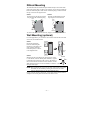
Grounding the Switch
Grounding and wire routing help limit the effects of noise due to
electromagnetic interference (EMI). Run the ground connection from the
ground screw to the grounding surface prior to connecting devices.
ATTENTION
This product is intended to be mounted to a well-grounded
mounting surface, such as a metal panel.
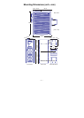
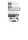
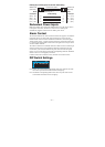
Wiring the Alarm Contact
The Alarm Contact consists of the two middle contacts of the terminal block on
the NI UES-3880’s top panel. You may refer to the next section for detailed
instructions on how to connect the wires to the terminal block connector, and
how to attach the terminal block connector to the terminal block receptor. In
this section, we explain the meaning of the two contacts used to connect the
Alarm Contact.
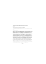
FAULT
FAULT
Top View
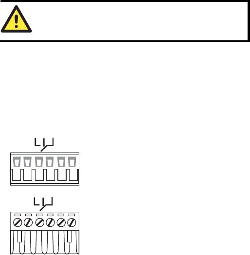
Front View
FAULT: The two middle contacts of the
6-contact terminal block connector are used to
detect both power faults and port faults. The two
wires attached to the Fault contacts form an open
circuit when:
1. The NI UES-3880 has lost power from one of
the DC power inputs.
OR
2. One of the ports for which the corresponding
PORT ALARM DIP Switch is set to ON is
not properly connected.
If neither of these two conditions is satisfied, the
Fault circuit will be closed.
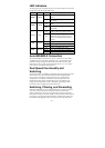
Wiring the Redundant Power Inputs
The top two contacts and the bottom two contacts of the 6-contact terminal
block connector on the NI UES-3880’s top panel are used for the NI
UES-3880’s two DC inputs. Top and front views of one of the terminal block
connectors are shown here.