


NI USB-6008/6009 User Guide and Specifications 18 ni.com
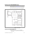
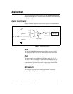
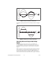
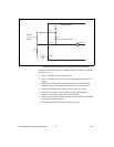
Figure 9. Example of a Differential 20 V Measurement
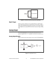
Connecting a signal greater than ±10 V on either pin results in a clipped
output.
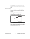
Figure 10. Exceeding ±10 V on AI Returns Clipped Output
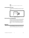
Connecting Referenced Single-Ended Voltage
Signals
To connect referenced single-ended voltage signals (RSE) to the
NI USB-6008/6009, connect the positive voltage signal to the desired
AI terminal, and the ground signal to a GND terminal, as illustrated in
Figure 11.
When no signals are connected to the analog input terminal, the internal
resistor divider may cause the terminal to float to approximately 1.4 V
when the analog input terminal is configured as RSE. This behavior is
normal and does not affect the measurement when a signal is connected.
–5
–10
–15
–20
20
15
10
5
0
Amplitude (V)
AI 1
AI 5
Result
–5
–10
–15
–20
20
15
10
5
0
Amplitude (V)
AI 1
AI 5
Result