


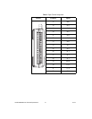
NI USB-6008/6009 User Guide and Specifications 22 ni.com
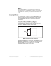
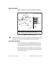
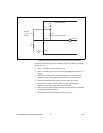
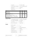
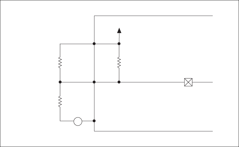
Figure 15. Example of Connecting an External User-Provided Resistor
Complete the following steps to determine the value of the user-provided
pull-up resistor:
1. Place an ammeter in series with the load.
2. Place a variable resistor between the digital output line and the +5 V
supply.
3. Adjust the variable resistor until the ammeter current reads as the
intended current. The intended current must be less than 8.5 mA.
4. Remove the ammeter and variable resistor from your circuit.
5. Measure the resistance of the variable resistor. The measured
resistance is the ideal value of the pull-up resistor.
6. Select a static resistor value for your pull-up resistor that is greater than
or equal to the ideal resistance.
7. Re-connect the load circuit and the pull-up resistor.
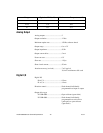
GND
P0.0
+5 V
Rp
Re
Rl
NI USB-6008/6009
Load
A
+5 V
Port Pad
4.7 kΩ Onboard Resistor
External
Pull-Up
Resistor