


Index
NI PXI-1052 User Manual I-4 ni.com
SCXI subsystem
control slot for PXI peripheral
module, 1-7
installation, filler panel, 2-10
overview, 1-8
service interval, 3-1
setting fan speed, 2-3
slot blocker, installation, 2-3
software (NI resources), C-1
specifications
backplane, A-6
dimensions (figure), A-8, A-9
electrical
AC input, A-1
DC output, A-2
electromagnetic compatibility, A-4
environmental, A-5
mechanical, A-6
pxi subsystem cooling, A-3
rack mount kit dimensions (figure), A-10
safety, A-3
star trigger (ST) slot
description, 1-6
P1 (J1) connector pinouts (table), B-4
P2 (J2) connector pinouts (table), B-5
star trigger and local bus routing
(figure), 1-8
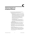
support, technical, C-1
system controller slot
description, 1-6
P1 (J1) connector pinouts (table), B-2
P2 (J2) connector pinouts (table), B-3
system reference clock, 1-8
T
technical support, C-1
testing power up, 2-4
training and certification (NI resources), C-1
trigger bus, 1-7
troubleshooting (NI resources), C-1
U
unpacking the PXI-1052, 1-1
V
voltage monitoring connector. See D-Sub
connector
voltages at voltage monitoring connector
(D-Sub) (table), 2-21
W
Web
professional services, C-1
technical support, C-1