


Chapter 1 Getting Started
PXI-1000 User Manual 1-6
©
National Instruments Corporation
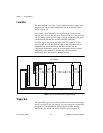
Local Bus
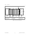
The PXI backplane’s local bus is a daisy-chained bus that connects each
peripheral slot with its adjacent peripheral slots to the left and right, as
shown in Figure 1-3.
For example, a given peripheral slot’s right local bus connects to the
adjacent slot’s left local bus and so on. Each local bus is 13 lines wide and
can pass analog signals between cards or provide a high-speed side-band
communication path that does not affect the PXI bandwidth.
Local Bus signals may range from high-speed TTL signals to analog
signals as high as 42 V. Initialization software keys adjacent boards to
prohibit the use of incompatible boards. This software uses the
configuration information specific to each peripheral board to evaluate
compatibility. This method is a flexible way to define local bus
functionality that is not limited by hardware keying.
Figure 1-3.
PXI Local Bus and Star Trigger Routing
Trigger Bus
The eight PXI trigger lines are bused to each slot. You can use the trigger
lines in a variety of ways. For example, you can use triggers to synchronize
the operation of several different PXI peripheral modules. In other
applications, one module can control carefully timed sequences of
System Controller Slot [1]
Star Trigger/Peripheral Slot [2]
Peripheral Slot [3]
Peripheral Slot [4]
Peripheral Slot [7]
Peripheral Slot [8]
Local
Bus
Local
Bus
Star Triggers
PCI Arbitration and Clock Signals
Local
Bus