


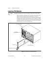

Chapter 2 Installation and Configuration
©
National Instruments Corporation 2-5 PXI-1000 User Manual
Remote Power Monitoring and Inhibiting Interface
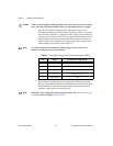
The PXI-1000 mainframe supports remote power monitoring and
inhibiting via a 9-pin D-sub connector located on the rear panel. Table 2-2
shows the pinout of the DB-9 connector.
You can use the Inhibit signal (active low) to turn off the power supply
outputs. To use this feature, connect the Inhibit pin (pin 5) to a Logic
Ground pin (pin 1 or 9). Make sure both the rear main power switch and
the front (standby) switch are in the ON position. As long as Inhibit is
pulled down, the power supply inhibits its DC outputs. DC output resumes
when Inhibit is no longer connected to ground. Note that the power
(standby) switch, located on the front of the chassis, uses this inhibiting
feature. For remote reset, connect a momentary switch between pin 5 and
pin 1 (or pin 9).
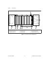
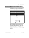
Table 2-2.
DB-9 Connector Pinout
DB-9 Pin Signal
1 Logic Ground
2 +5 V
3 Reserved
4 +3.3 V
5 Inhibit*
6 +12 V
7 Reserved
8 –12 V
9 Logic Ground
54321
9876