


Index
©
National Instruments Corporation I-3 PXI-1000 User Manual
power supply
remote power monitoring and inhibit
interface, 2-5
universal, 2-3
voltages at power monitoring connector
(DB-9) (table), 2-4
power up, testing, 2-3 to 2-4
PXI-1000
cooling air intake (figure), 2-2
dimensions (figure), A-7
features, 1-2 to 1-3
front view (figure), 1-4
installation (See installation and
configuration)
maintenance (See maintenance of
PXI-1000)
optional equipment, 1-2
power cables required (table), 1-1 to 1-2
rear view (figure), 1-5
requirements for getting started,
1-1 to 1-2
specifications (See specifications)
unpacking, 1-1
PXI-1000 backplane, 1-3 to 1-7
interoperability with CompactPCI, 1-3
local bus, 1-6
peripheral slots, 1-5
specifications (table), A-5
Start Trigger slot, 1-5
System Controller slot, 1-5
system reference clock, 1-7
PXI_CLK10, 1-7
PXI_CLK10_IN pin, 1-7
R
rack mounting, 2-2
remote power monitoring and inhibit
interface, 2-5
S
safety ground, connecting, 2-3
safety specifications (table), A-3
service interval, 3-1
specifications, A-1 to A-7
backplane, A-5
cooling, A-3
electrical, A-1 to A-2
environmental, A-4
mechanical, A-7
safety, A-3
Star Trigger (ST) slot
description, 1-5
P1 (J1) connector pinouts (table), B-4
P2 (J2) connector pinouts (table), B-5
triggers for peripheral slots (figure), 1-6
static discharge damage (caution), 3-1
System Controller slot
description, 1-5
P1 (J1) connector pinouts (table), B-2
P2 (J2) connector pinouts (table), B-3
system reference clock, 1-7
T
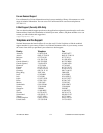
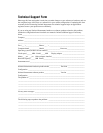
technical support, C-1 to C-2
telephone and fax support, C-2
trigger bus, 1-6 to 1-7
troubleshooting the PXI-1000, 3-4
U
unpacking the PXI-1000, 1-1
V
voltages at power monitoring connector
(DB-9) (table), 2-4