


©
National Instruments Corporation B-1 PXI-1000 User Manual
B
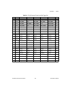
Pinouts
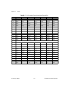
This appendix describes the P1 and P2 connector pinouts for the PXI-1000
backplane.
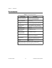
Table B-1 shows the P1 (J1) connector pinout for the System Controller
slot.
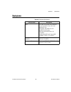
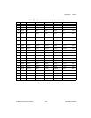
Table B-2 shows the P2 (J2) connector pinout for the System Controller
slot.
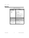
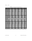
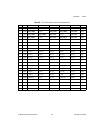
Table B-3 shows the P1 (J1) connector pinout for the Star Trigger slot.
Table B-4 shows the P2 (J2) connector pinout for the Star Trigger slot.
Table B-5 shows the P1 (J1) connector pinout for the peripheral slots.
Table B-6 shows the P2 (J2) connector pinout for the peripheral slots.
Note
PXI signals are shown in boldface.