


Index
PXI-1000 User Manual I-2
©
National Instruments Corporation
I
Inhibit signal, turning off power supply
outputs, 2-5
installation and configuration, 2-1 to 2-7
chassis initialization file, 2-7
connecting safety ground, 2-3
connecting to AC mains power, 2-3 to 2-4
filler panel installation, 2-7
module installation, 2-6 to 2-7
CompactPCI or PXI module
(figure), 2-6
ejector/injector handle position
(figure), 2-7
rack mounting, 2-2
remote power monitoring and inhibit
interface, 2-5
setting fan speed, 2-2
site considerations, 2-1 to 2-2
testing power up, 2-3 to 2-4
unpacking the PXI-1000, 1-1
J
J1 connector pinouts. See P1 (J1) connector
pinouts.
J2 connector pinouts. See P2 (J2) connector
pinouts.
L
local bus
routing (figure), 1-6
signals, 1-6
M
maintenance of PXI-1000, 3-1 to 3-4
cleaning
exterior cleaning, 3-2
fan filters, 3-2
interior cleaning, 3-2
precautions before cleaning, 3-1
preparation, 3-1
resetting AC mains circuit breaker, 3-3
service interval, 3-1
static discharge damage (caution), 3-1
troubleshooting, 3-4
mechanical specifications, A-6 to A-7
O
optional equipment, 1-2
P
P1 (J1) connector pinouts
peripheral slot (table), B-6
Star Trigger slot (table), B-4
System Controller slot (table), B-2
P2 (J2) connector pinouts
peripheral slot (table), B-7
Star Trigger slot (table), B-5
System Controller slot (table), B-3
peripheral slots
overview, 1-5
P1 (J1) connector pinouts (table), B-6
P2 (J2) connector pinouts (table), B-7
pinouts
DB-9 connector (table), 2-5
P1 (J1) connector
peripheral slot (table), B-6
Star Trigger slot (table), B-4
System Controller slot (table), B-2
P2 (J2) connector
peripheral slot (table), B-7
Star Trigger slot (table), B-5
System Controller slot (table), B-3
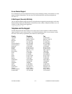
power cables (table), 1-1 to 1-2
power monitoring connector. See DB-9
connector.
power problems, troubleshooting, 3-4