


© National Instruments Corporation I-1 SCXI-1190/1191 User Manual
Index
A
auto-detection of modules, 1-8 to 1-9
B
block diagram of SCXI-119X, 2-2
C
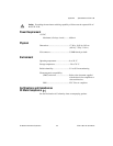
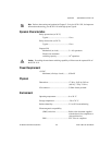
certifications and compliances
SCXI-1190, A-3
SCXI-1191, A-5
common questions, B-1 to B-2
configuration, 1-7 to 1-11
auto-detecting modules, 1-8 to 1-9
manually adding modules, 1-9 to 1-10
self-test verification, 1-10
steps for, 1-7 to 1-8
troubleshooting self-test verification,
1-10 to 1-11
connecting SCXI-119X to DAQ device
DAQ device or computer-based instrument,
1-4to1-6
in PXI combination chassis, 1-6 to 1-7
connecting signals. See signal connections.
contact protection, 2-3
conventions used in manual, vi
D
DAQ device. See connecting SCXI-119X to
DAQ device.
diagnostic resources, online, C-1
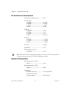
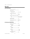
dynamic characteristics
SCXI-1190, A-2 to A-3
SCXI-1191, A-5
E
environment specifications
SCXI-1190, A-3
SCXI-1191, A-5
expanding RF multiplexer, 2-6
H
hardware installation. See installation.
I
input characteristics
SCXI-1190, A-1
SCXI-1191, A-4
installation, 1-2 to 1-7
connecting SCXI-119X to DAQ device
DAQ device or computer-based
instrument, 1-4 to 1-6
in PXI combination chassis, 1-6 to 1-7
removing SCXI-119X, 1-12 to 1-14
from Measurement & Automation
Explorer, 1-13 to 1-14
from SCXI chassis, 1-12 to 1-13
into SCXI chassis, 1-3 to 1-4
software installation, 1-1 to 1-2
unpacking, 1-2
isolation, defined, B-2
M
Measurement & Automation Explorer
auto-detecting modules, 1-8 to 1-9
configuration procedure, 1-7 to 1-8
manually adding modules, 1-9 to 1-10
removing SCXI-119X, 1-13 to 1-14
self-test verification, 1-10