


CHAPTER 1 OVERVIEW
User’s Manual U14337EJ1V0UM00
16
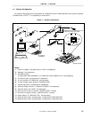
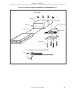
1.6 Connection between IE-703002-MC and IE-703040-MC-EM1
The procedure for connecting the IE-703002-MC and IE-703040-MC-EM1 is described below.
Caution Connect carefully so as not to break or bend connector pins.
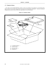
<1> Remove the pod cover (upper and lower) of the IE-703002-MC.
<2> Replace the crystal oscillator mounted in the pod of the IE-703002-MC with the crystal oscillator supplied (20
MHz) or an arbitrary oscillator (user’s frequency).
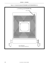
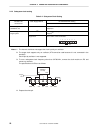
<3> Set the PGA socket lever of the IE-703040-MC-EM1 to the OPEN position as shown in Figure 1-4 (b).
<4> Connect the IE-703040-MC-EM1 to the PGA socket at the back of the IE-703002-MC pod (refer to Figure 1-4
(c)). When connecting, position the IE-703002-MC and IE-703040-MC-EM1 so that they are horizontal.
<5> Set the PGA socket lever of the IE-703040-MC-EM1 to the CLOSE position as shown in Figure 1-4 (b).
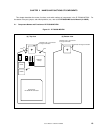
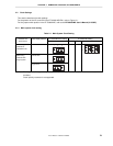
<6> Set the IE-703002-MC pod jumpers (JP1 to JP4).
Open JP1 and JP3 (Remove the jumper contact and attach the removed jumper contact to one of the jumper
pins to avoid losing it.)
Retain the factory settings of JP2 (pins 1 and 2 shorted, and pins 5 and 6 shorted).
Short pins 2 and 3 of JP4.
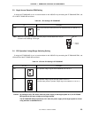
<7> Fix the IE-703040-MC-EM1 between the IE-703002-MC pod covers (upper and lower) with the plastic screws
(supplied with the IE-703002-MC).
<8> Fix the IE-703002-MC pod cover (upper) end with nylon rivets.
Remark
For the JP1 setting, refer to
2.3 Illegal Access Detection ROM Setting
. For JP3 and JP4, refer
to
2.4 CPU Operation Voltage Range Switch Setting
.