


CHAPTER 2 NAMES AND FUNCTIONS OF COMPONENTS
User’s Manual U14337EJ1V0UM00
21
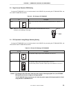
2.2 Clock Settings
This section describes the clock settings.
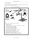
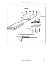
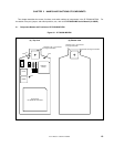
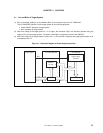
For the position of the JP1 and JP2 in the IE-703040-MC-EM1, refer to Figure 2-1.
For the jumper switch position in the IE-703002-MC, refer to the
IE-703002-MC User’s Manual (U11595E)
.
2.2.1 Main system clock setting
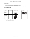
Table 2-1. Main System Clock Setting
IE-703040-MC-EM1 Setting IE-703002-MC SettingEmulator Use
Environment
Clock Supply Method
JP1 SW1 SW2 JP2
When using
emulator as
standalone unit
Internal clock
12
3
ON
1
7
8
2
Internal clock
12
3
When using
emulator with
target system
Target clock
Note
12
3
ON
Note
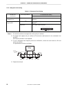
The target clock supports only an oscillator (X2 cannot be used because it is not connected in the
emulator).
Clock input by resonator is not supported.