


CHAPTER 2 INSTALLATION
– 32 –
NWA-008869-001 Rev.1.0
atch2001.fm
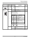
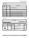
The figure in the SWITCH NAME column and the position of in the SETTING POSITION col-
umn indicate the standard setting of the switch. When the switch is not set as shown by the figure and
, the setting of the switch varies with the system concerned.
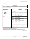
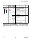
SWITCH NAME
SWITCH
NUMBER
SETTING
POSITION
FUNCTION CHECK
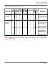
DK (Connector)
02 Ground detection
01 Ground sending
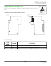
JP0 (Jumper pin)
For normal operation
(Battery backup ON)
DOWN
Not used
(Battery backup OFF)
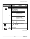
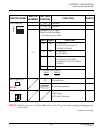
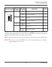
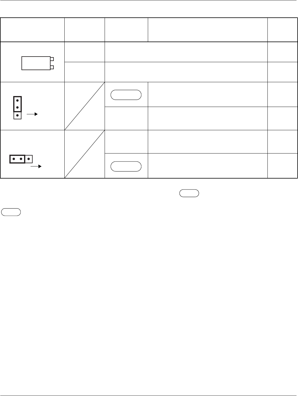
JP1 (Jumper pin)
RIGHT For using external hold tone source
For using internal hold tone source
01
02
Front
UP
Front
LEFT
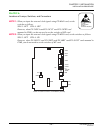
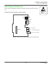
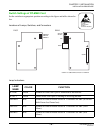
INSTALLATION PROCEDURE