


CHAPTER 2 INSTALLATION
– 37 –
NWA-008869-001 Rev.1.0
atch2001.fm
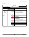
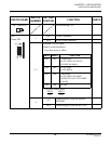
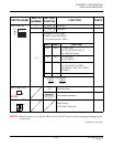
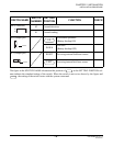
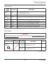
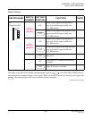
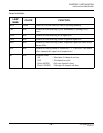
Switch Settings
The figure in the SWITCH NAME column and the position of in the SETTING POSITION col-
umn indicate the standard setting of the switch. When the switch is not set as shown by the figure and
, the setting of the switch varies with the system concerned.
Continued on next page
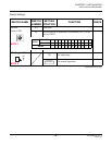
SWITCH NAME
SWITCH
NUMBER
SETTING
POSITION
FUNCTION CHECK
SW
(Piano Key SW)
1
NOTE 1
NOTE 2
ON
Source clock signal from network is
sent to the PLO0 input on MP card
(1.5 MHz clock).
Source clock signal from network is not
sent to the PLO0 input on MP card
(1.5 MHz clock).
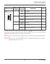
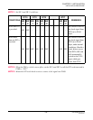
2
NOTE 1
NOTE 2
ON
Source clock signal from network is
sent to the PLO1 input on MP card
(1.5 MHz clock).
Source clock signal from network is not
sent to the PLO1 input on MP card
(1.5 MHz clock).
3 Not used
4
ON
WAN port or T1 interface for PBX are
available.
Only WAN port is available.
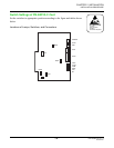
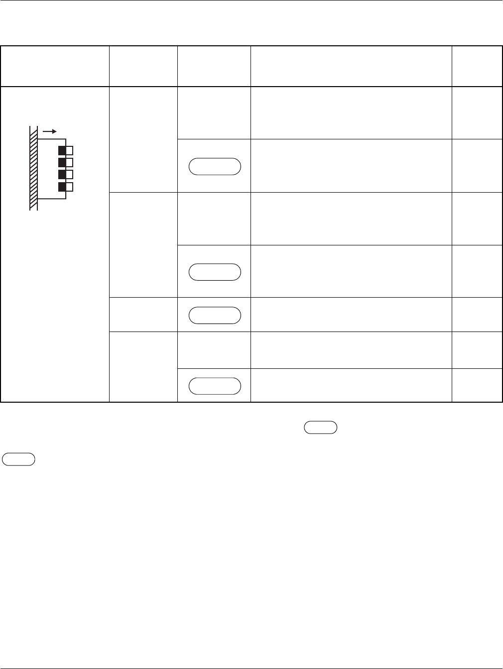
1
2
3
4
ON
OFF
OFF
OFF
OFF
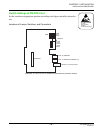
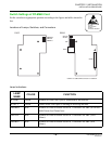
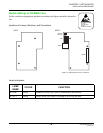
INSTALLATION PROCEDURE