


µ
PD75P308
16
Ceramic
*3
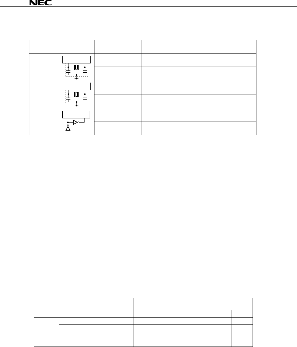
Oscillation
frequency (fXX)
*1
Oscillation stabilization After VDD came to MIN.
time
*2
of oscillation voltage range
Crystal Oscilaltion
frequency (fXX)
*1
Oscillation stabilization
time
*2
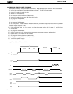
External Clock X1 input frequency
(fX)
*1
X1 input high-, low-level
widths (tXH, tXL)
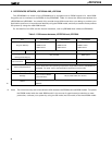
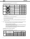
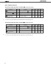
MAIN SYSTEM CLOCK OSCILLATOR CIRCUIT CHARACTERISTICS
(T
a = -10 to +70°C, VDD = 5 to ±5 V)
Oscillator Item Conditions MIN. TYP. MAX. Unit
X1 X2
C1 C2
V
DD
X1 X2
C1 C2
V
DD
X1 X2
PD74HCU04
µ
1.0 5.0
*4
MHz
4ms
1.0 4.19 5.0
*4
MHz
10 ms
1.0 5.0
*4
MHz
100 500 ns
Recommended
Constants
*1: The oscillation frequency and X1 input frequency are indicated only to express the characteristics of the
oscillator circuit.
For instruction execution time, refer to AC Characteristics.
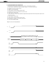
2: Time required for oscillation to stabilize after V
DD reaches the minimum value of the oscillation voltage
range or the STOP mode has been released.
3: The oscillators below are recommended.
4: When the oscillation frequency is 4.19 MHz < fx ≤ 5.0 MHz, do not select PCC = 0011 as the instruction
execution time: otherwise, one machine cycle is set to less than 0.95
µ
s, falling short of the rated
minimum value of 0.95
µ
s.
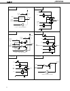
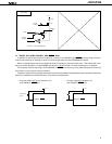
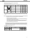
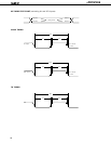
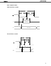
Caution: When using the oscillation circuit of the main system clock, wire the portion enclosed in dotted
line in the figures as follows to avoid adverse influences on the wiring capacity:
• Keep the wiring length as short as possible.
• Do not cross the wiring over the other signal lines. Do not route the wiring in the vicinity of
lines through which a high alternating current flows.
• Always keep the ground point of the capacitor of the oscillator circuit at the same potential
as V
DD. Do not connect the power source pattern through which a high current flows.
• Do not extract signals from the oscillation circuit.
★
★
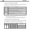
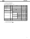
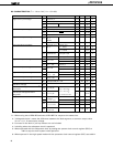
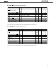
CSA 2.00MG 30 30 4.75 5.25
CSA 4.19MG 30 30 4.75 5.25
CSA 4.19MGU 30 30 4.75 5.25
CST 4.19MG 30 pF (internal) 30 pF (internal) 4.75 5.25
C1
Murata
Mfg.
Co., Ltd.
Manufac-
turer
MAX.MIN.
Oscillation
Voltage Range [V]
C2
External Capacitance [pF]
Product Name
RECOMMENDED OSCILLATION CIRCUIT CONSTANTS
MAIN SYSTEM CLOCK: CERAMIC OSCILLATOR (Ta = -10 to +70°C)