


µ
PD75P308
25
Released by RESET
Released by interrupt
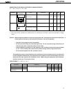
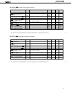
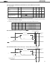
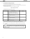
LOW-VOLTAGE DATA RETENTION CHARACTERISTICS OF DATA MEMORY IN STOP MODE
(T
a = -10 to +70°C)
0
µ
s
2
17
/fX ms
*
3
ms
Parameter Symbol Conditions MIN. TYP. MAX. Unit
tSREL
Data Retention Supply
Voltage
Data Retention Supply
Current*
1
Release Signal Set Time
Oscillation Stabilization
Wait Time*
2
2.0 6.0 V
*1: Does not include current folowing through internal pull-up resistor
2: The oscillation stabilization wait time is the time during which the CPU is stopped to prevent unstable
operation when oscillation is started.
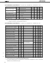
3: Depends on the setting of the basic interval timer mode register (BTM) as follows:
BTM3 BTM2 BTM1 BTM0 WAIT time ( ): fX = 4.19 MHz
—0 0— 2
20
/fX (approx. 250 ms)
—0 1— 2
17
/fX (approx. 31.3 ms)
—1 0— 2
15
/fX (approx. 7.82 ms)
—1 1— 2
13
/fX (approx. 1.95 ms)
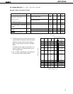
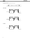
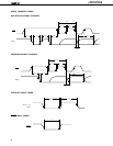
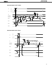
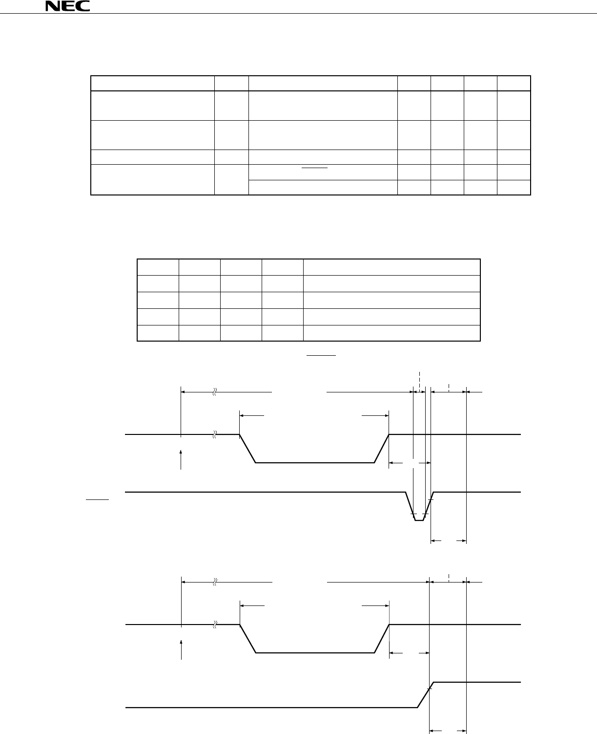
DATA RETENTION TIMING (releasing STOP mode by RESET)
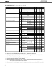
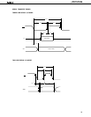
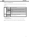
DATA RETENTION TIMING (standby release signal: releasing STOP mode by interrupt)
STOP mode
Data retention mode
STOP instruction execution
V
DD
VDDDR
tSREL
tWAIT
Operation
mode
HALT mode
Standby release signal
(interrupt request)
I
DDDR VDDDR = 2.0V 0.1 10
µ
A
STOP mode
Data retention mode
STOP instruction
execution
V
DD
RESET
V
DDDR
t
SREL
t
WAIT
Operation
mode
Internal reset operation
HALT mode
VDDDR
tWAIT