


µ
PD75P308
19
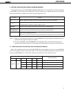
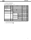
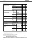
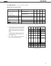
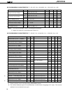
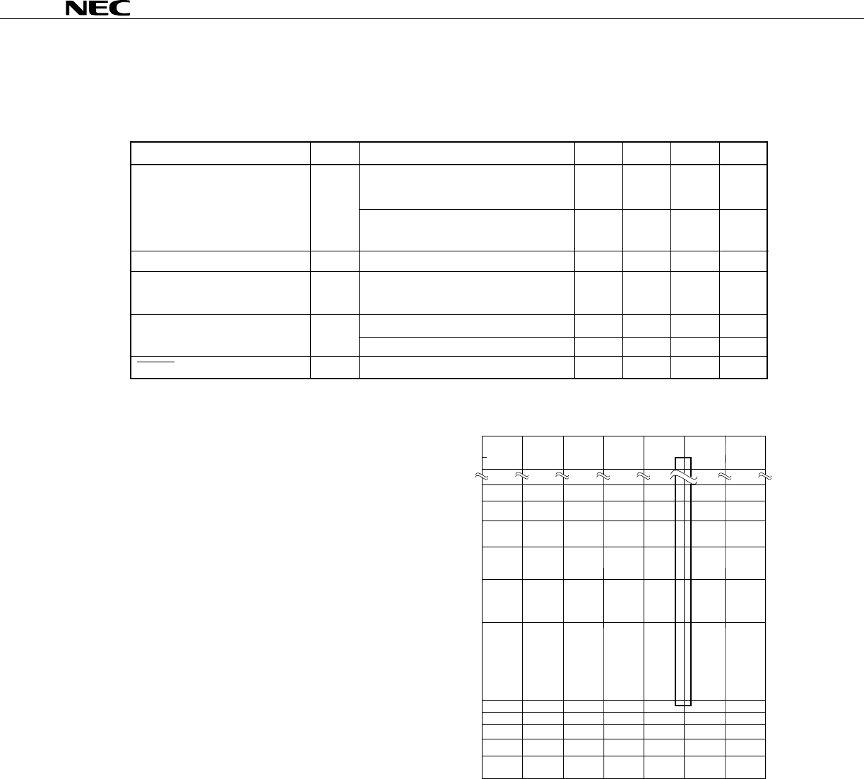
AC CHARACTERISTICS (Ta = -10 to + 70°C, VDD = 5V ±5%)
Operation Other Than Serial Transfer
Parameter Symbol Conditions MIN. TYP. MAX. Unit
w/main system clock
w/subsystem clock
INT0
KR0-7, INT1, 2, 4
tCY
fTI
tTIH, tTIL
tINTH,
tINTL
tRSL
CPU Clock Cycle Time*
1
(Minimum Instruction
Execution Time
= 1 Machine Cycle)
TI0 Input Frequency
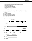
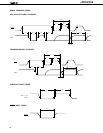
TI0 Input High-, Low-Level
Widths
Interrupt Input High-, Low-Level
Widths
RESET Low-Level Width
0.95 64
µ
s
114 122 125
µ
s
0 1 MHz
0.48
µ
s
*2
µ
s
10
µ
s
10
µ
s
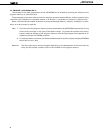
0 1 2 3 4 5 6
0.5
1
2
3
4
5
6
60
64
70
(with main system clock)
Cycle time t [ s]
cy
µ
Supply voltage V [V]
DD
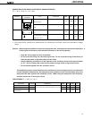
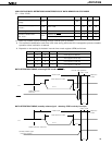
t vs V
cy DD
* 1: The CPU clock (Φ) cycle time is determined
by the oscillation frequency of the connected
oscillator, system clock control register
(SCC), and processor clock control register
(PCC).
The figure on the right is cycle time t
CY vs.
supply voltage V
DD characteristics at the
main system clock.
2: 2tCY or 128/fXX depending on the setting of
the interrupt mode register (IM0).